Mix fast strip 71
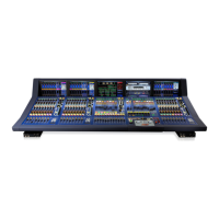
XL8 Control Centre
Operator Manual
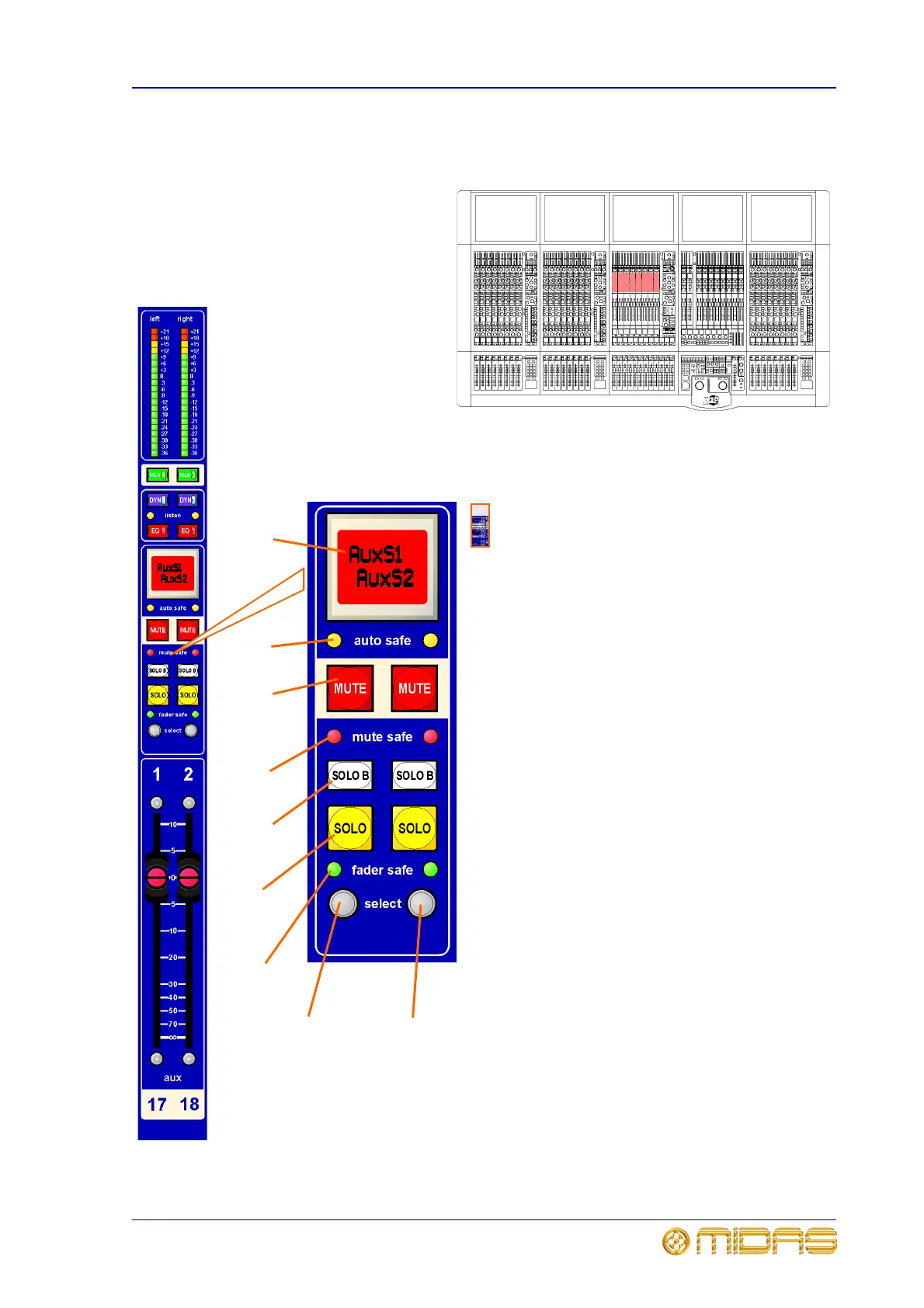
LCD and solo
Labelling and output channel selection.
1 Output channel select switch (backlit). This
LCD switch selects single output channel bus, left
and right output channel pairs (for example, for
VCA routing functions) and ‘follow selects’ stereo
aux mixes onto the bus area of input fast zone.
Bus name and switch’s backlight colour can be
configured to suit. Top name is for left channel
and bottom one for right channel.
2 auto safe LEDs illuminate if the channel
has been removed from scene recall (this does
not affect action of auto mutes and VCA control
groups).
3 MUTE switches mute all post-processing
signals leaving the channel. They have their own
illumination to confirm this action. In addition to
scene recall, muting can be remote from auto
mute masters.
4 mute safe LEDs illuminate if mute has been
removed from the scene recall and auto mute
action.
5 SOLO B changes the operation of the SOLO
switch so that it routes signals to the Monitor B
section of the console, see “monitor a and b
output panel and meters” on page 116.
6 SOLO activates signal routing to the
Monitor A section of the console, see “monitor a
and b output panel and meters” on page 116.
7 fader safe LEDs illuminate if the fader has
been removed from scene recall and control from
VCA control group faders.
8 Channel quick access select button selects
the channel’s mix section to the mix bay output
channel strip. Left-hand button (8a) selects odd
numbered channel to the left and right-hand
button (8b) selects even numbered channel to
the right. With both channels linked for stereo,
both buttons operate on the pair.
1
2
3
4
5
6
7
8a
8b