Channel configuration 41
XL8 Control Surface
Operator Manual
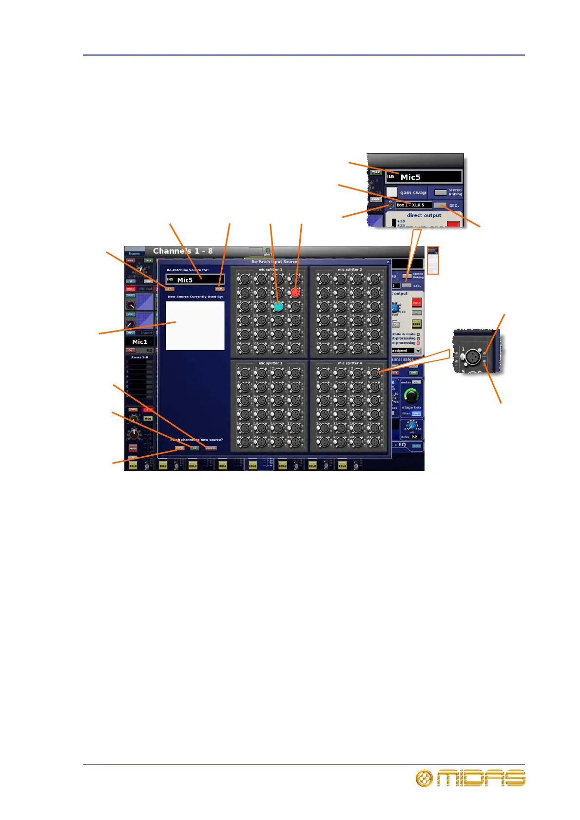
Input channel source (GUI only)
The input channel’s current source is displayed in a text box in the GUI input channel
strip (adjacent to the XLR connector symbol). The adjacent src. button opens a “Re-
Patch Input Source” window that provides a visual representation of the rear of the four
mic splitters and allows you to ‘re-patch’ an input channel’s source.
1 LEFT button scrolls through the virtual
connectors one at a time. Goes to next lowest and
appears to travel from right to left across the mic
splitter.
2 Name field shows currently selected input
channel. Permanent ID is to the left (for example,
“IN5”) and, in larger text, the user-configured name is
to the right (for example, “Mic5”).
3 RIGHT button scrolls through the virtual
connectors one at a time. Goes to next highest and
appears to travel from left to right across the mic
splitter.
4 Blue translucent circle used to select new input
source. When clicking on a new input the blue circle
moves to that input. The “New Source Currently Used
By:” panel (item 9) will show which input channels are
configured to that source. Click APPLY to patch the
currently selected channel to the new input source.
5 Red translucent circle identifies the current input
source of currently selected channel. Moves
accordingly with presses of the LEFT and RIGHT
buttons (also when changing input channel selection
via the control surface).
6 CANCEL button exits screen, without saving any
of the current session’s re-patch settings.
7 OK button exits screen, saving the current
session’s re-patch settings.
8 APPLY button accepts new source allocation,
highlighted by the blue circle.
9 “New Source Currently Used By:” panel shows
the input channels allocated to the currently selected
input source, highlighted by the blue circle.
10 src. button opens the “Re-patch Input Source”
window.
11 Current source of selected input channel.
Identifies the mic splitter (box number) and connector
(XLR number).
12 XLR connector symbol.
13 check LED mimics action of the corresponding
LED on the mic splitter by illuminating to indicate that
a channel on the XL8 is selected to this input.
14 48V LED mimics the action of corresponding LED
on the mic splitter by illuminating to indicate that 48V
phantom voltage is switched on for this input.
1
2
3
9
8
7
6
5
4
10
11
12
2
13
14