Diagnostics 267
XL8 Control Centre
Operator ManualQuick Reference Guide
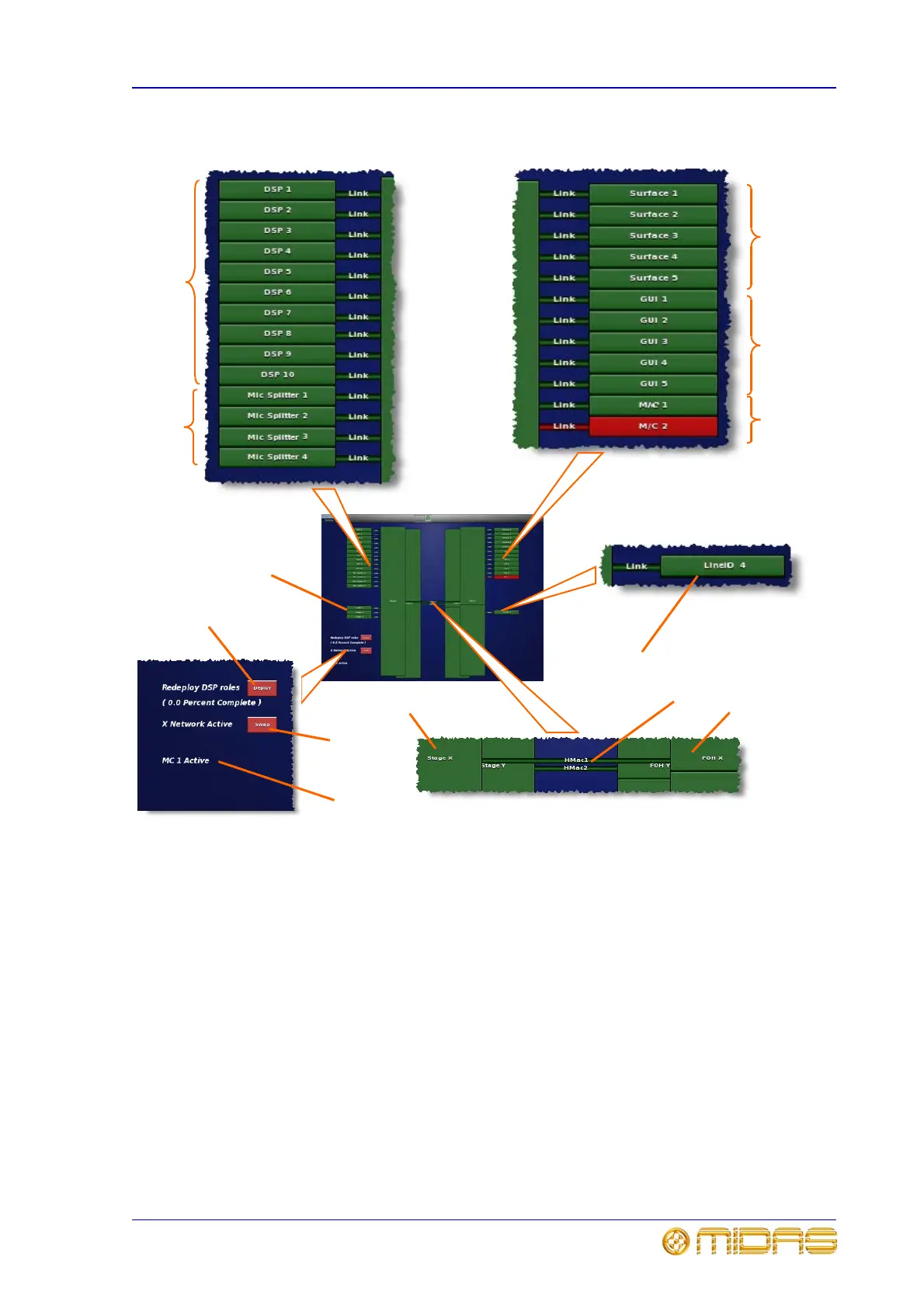
Diagnostic screen description
1 DSPs 1 - 10: shows the unit and connection
status of the DSP units.
2 Mic Splitter 1 - 4: shows the unit and
connection status of the mic splitters.
3 Surface 1 - 5: shows the hardware and
connection status of each bay’s control surface.
4 GUI 1 - 5: shows the hardware and connection
status of each bay’s GUI screen.
5 M/C 1 and 2: shows the hardware and
connection status of the two master controllers.
6 LINE I/O 1 - 4: shows the unit and connection
status of the I/O units.
7 HMac 1 and 2: shows the status of the snake
connections (X and Y, respectively) between control
centre and router.
8 FOH X: status of the control centre’s internal
8-port X router. (FOH Y is the Y equivalent.)
9 Stage X: status of the 20-port external X router
on the stage. (Stage Y is the Y equivalent.)
10 Deploy button for configuring new DSP units, for
example, when you have just received a replacement
unit. Pressing this button loads the networked DSP
units with default software.
11 Swap button for swapping the active network
over from X to Y.
12 Message for showing you which master controller
is currently active; master controller 1 in this
example.
2
1
10
12
11
3
4
5
6
7
8
9
6