84 Chapter 5: Mix Bay
XL8 Control Centre
Operator Manual
Returns
The diagram right abstractly shows the
different groups of controls on each return
channel. It does not necessarily show the
linear order of processing of the signal in
that channel, as this is variable according
to a variety of options.
In this section we will look at each of these
groups of controls.
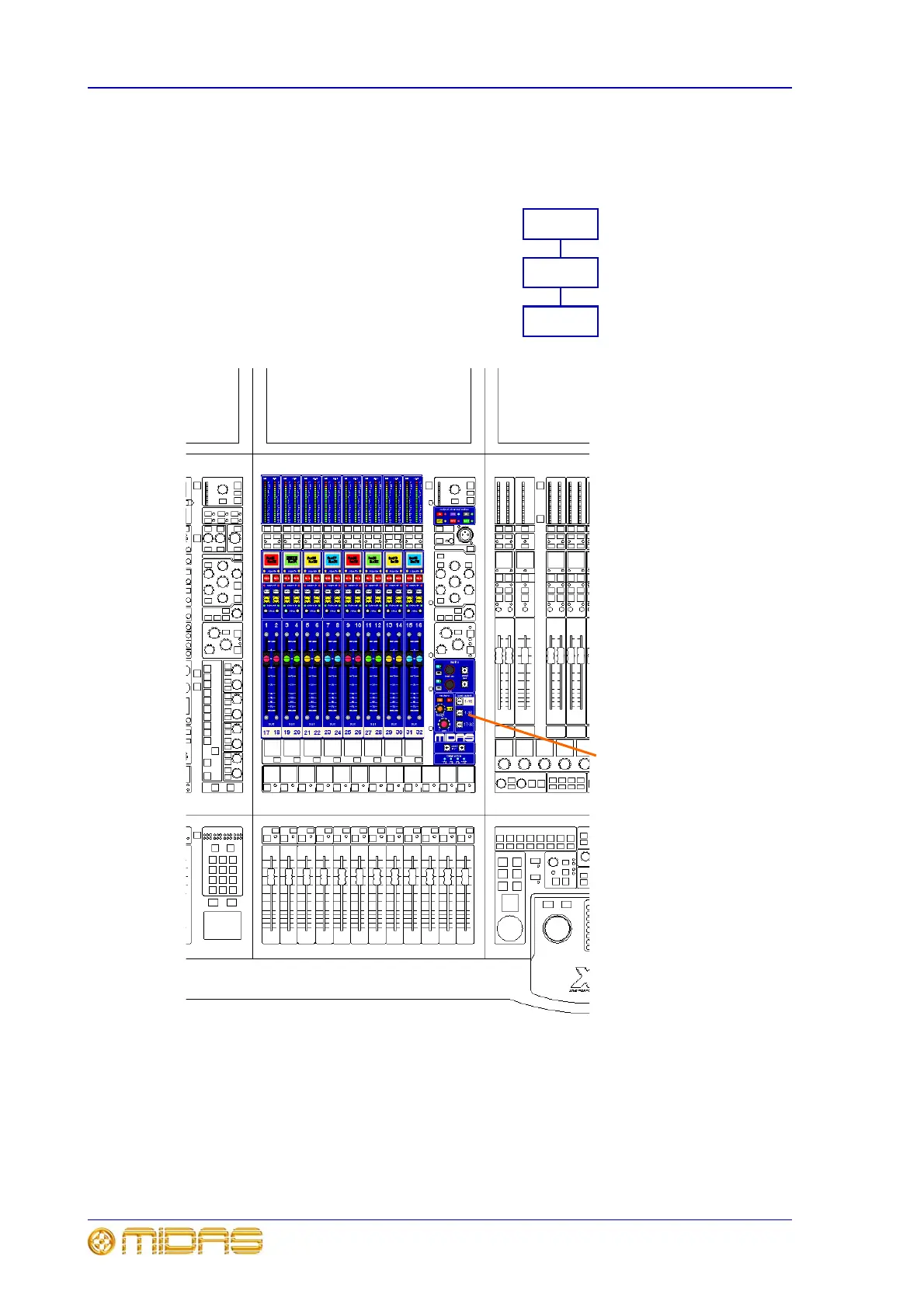
Diagram below shows the return-related
control surface areas on the mix bay.
Return channel
signal path
Configuration controls; see
page 85
Fader and master controls;
see page 88
Matrix outputs; see page 86
This button pages the output
section to address the returns.
This diagram shows the controls
that are operational when the
returns are paged to the output
section.
 Loading...