UM10462 All information provided in this document is subject to legal disclaimers. © NXP B.V. 2016. All rights reserved.
User manual Rev. 5.5 — 21 December 2016 134 of 523
NXP Semiconductors
UM10462
Chapter 8: LPC11U3x/2x/1x Pin configuration
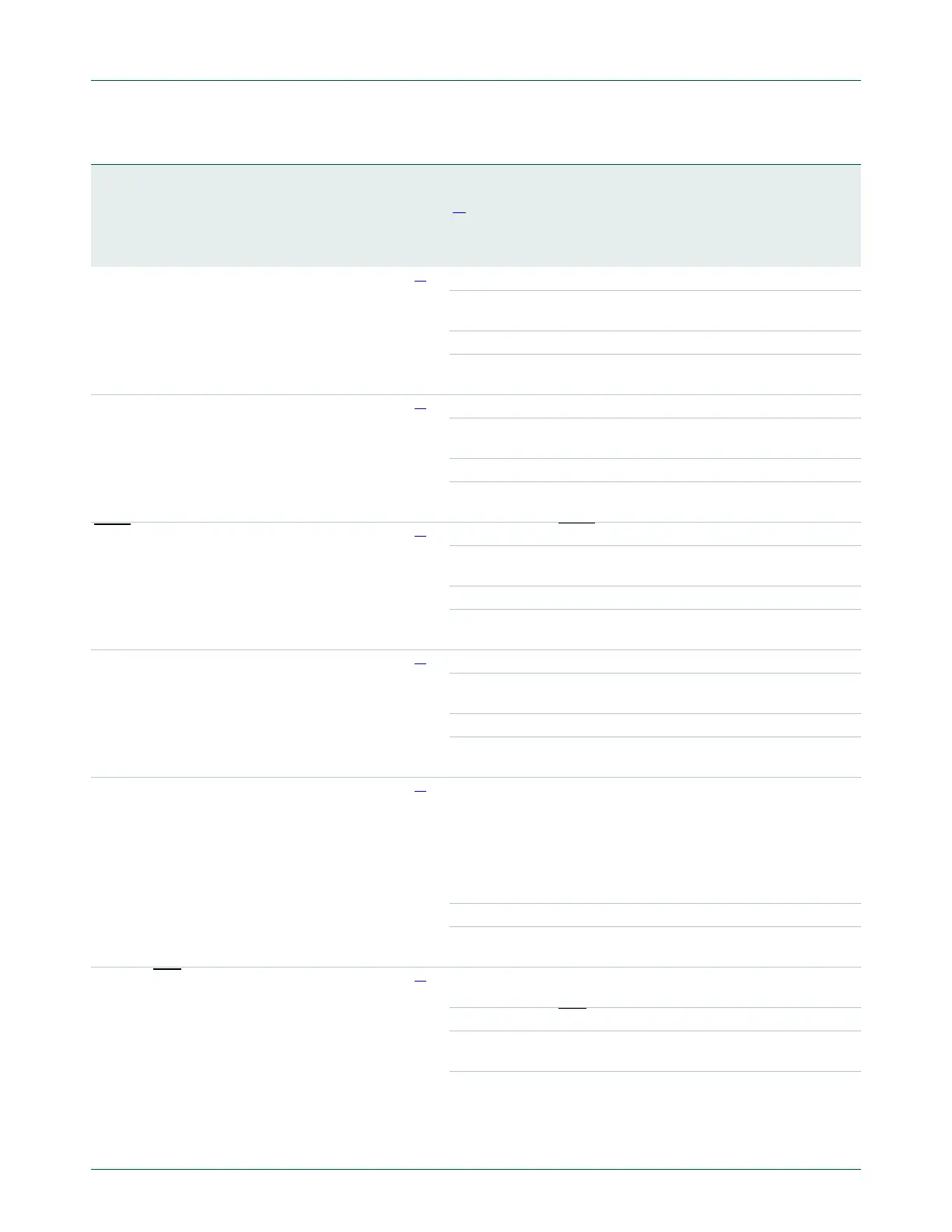
TMS/PIO0_12/AD1/
CT32B1_CAP0
22 33 C7
[6]
I; PU I TMS — Test Mode Select for JTAG interface.
-I/OPIO_12 — General purpose digital input/output
pin.
-IAD1 — A/D converter, input 1.
-ICT32B1_CAP0 — Capture input 0 for 32-bit
timer 1.
TDO/PIO0_13/AD2/
CT32B1_MAT0
23 34 C8
[6]
I; PU O TDO — Test Data Out for JTAG interface.
-I/OPIO0_13 — General purpose digital
input/output pin.
-IAD2 — A/D converter, input 2.
-OCT32B1_MAT0 — Match output 0 for 32-bit
timer 1.
TRST
/PIO0_14/AD3/
CT32B1_MAT1
24 35 B7
[6]
I; PU I TRST — Test Reset for JTAG interface.
-I/OPIO0_14 — General purpose digital
input/output pin.
-IAD3 — A/D converter, input 3.
-OCT32B1_MAT1 — Match output 1 for 32-bit
timer 1.
SWDIO/PIO0_15/AD4/
CT32B1_MAT2
25 39 B6
[6]
I; PU I/O SWDIO — Serial wire debug input/output.
-I/OPIO0_15 — General purpose digital
input/output pin.
-IAD4 — A/D converter, input 4.
-OCT32B1_MAT2 — Match output 2 for 32-bit
timer 1.
PIO0_16/AD5/
CT32B1_MAT3/WAKEUP
26 40 A6
[6]
I; PU I/O PIO0_16 — General purpose digital
input/output pin. In Deep power-down mode,
this pin functions as the WAKEUP pin with 20 ns
glitch filter. Pull this pin HIGH externally to enter
Deep power-down mode. Pull this pin LOW to
exit Deep power-down mode. A LOW-going
pulse as short as 50 ns wakes up the part.
-IAD5 — A/D converter, input 5.
-OCT32B1_MAT3 — Match output 3 for 32-bit
timer 1.
PIO0_17/RTS
/
CT32B0_CAP0/SCLK
30 45 A3
[3]
I; PU I/O PIO0_17 — General purpose digital
input/output pin.
-ORTS
— Request To Send output for USART.
-ICT32B0_CAP0 — Capture input 0 for 32-bit
timer 0.
-I/OSCLK — Serial clock input/output for USART in
synchronous mode.
Table 132. LPC11U1x pin description
…continued
Symbol
Pin HVQFN33
Pin LQFP48
Ball TFBGA48
Reset
state
[1]
Type Description

 Loading...


