UM10462 All information provided in this document is subject to legal disclaimers. © NXP B.V. 2016. All rights reserved.
User manual Rev. 5.5 — 21 December 2016 144 of 523
NXP Semiconductors
UM10462
Chapter 8: LPC11U3x/2x/1x Pin configuration
PIO1_21/DCD/MISO1 - 26 35
[3]
I; PU I/O PIO1_21 — General purpose digital input/output pin.
-IDCD
— Data Carrier Detect input for USART.
-I/OMISO1 — Master In Slave Out for SSP1.
PIO1_22/RI
/MOSI1 - 38 51
[3]
I; PU I/O PIO1_22 — General purpose digital input/output pin.
-IRI
— Ring Indicator input for USART.
-I/OMOSI1 — Master Out Slave In for SSP1.
PIO1_23/CT16B1_MAT1/
SSEL1
-1824
[3]
I; PU I/O PIO1_23 — General purpose digital input/output pin.
-OCT16B1_MAT1 — Match output 1 for 16-bit timer 1.
-I/OSSEL1 — Slave select for SSP1.
PIO1_24/CT32B0_MAT0 - 21 27
[3]
I; PU I/O PIO1_24 — General purpose digital input/output pin.
-OCT32B0_MAT0 — Match output 0 for 32-bit timer 0.
PIO1_25/CT32B0_MAT1 - 1 2
[3]
I; PU I/O PIO1_25 — General purpose digital input/output pin.
-OCT32B0_MAT1 — Match output 1 for 32-bit timer 0.
PIO1_26/CT32B0_MAT2/
RXD
-1114
[3]
I; PU I/O PIO1_26 — General purpose digital input/output pin.
-OCT32B0_MAT2 — Match output 2 for 32-bit timer 0.
-IRXD — Receiver input for USART.
PIO1_27/CT32B0_MAT3/
TXD
-1215
[3]
I; PU I/O PIO1_27 — General purpose digital input/output pin.
-OCT32B0_MAT3 — Match output 3 for 32-bit timer 0.
-OTXD — Transmitter output for USART.
PIO1_28/CT32B0_CAP0/
SCLK
-2431
[3]
I; PU I/O PIO1_28 — General purpose digital input/output pin.
-ICT32B0_CAP0 — Capture input 0 for 32-bit timer 0.
-I/OSCLK — Serial clock input/output for USART in
synchronous mode.
PIO1_29/SCK0/
CT32B0_CAP1
-3141
[3]
I; PU I/O PIO1_29 — General purpose digital input/output pin.
-I/OSCK0 — Serial clock for SSP0.
-ICT32B0_CAP1 — Capture input 1 for 32-bit timer 0.
PIO1_31 - 25 -
[3]
I; PU I/O PIO1_31 — General purpose digital input/output pin.
USB_DM 13 19 25
[7]
F-USB_DM — USB bidirectional D line.
USB_DP 14 20 26
[7]
F-USB_DP — USB bidirectional D+ line.
XTALIN 4 6 8
[8]
- - Input to the oscillator circuit and internal clock generator
circuits. Input voltage must not exceed 1.8 V.
XTALOUT 5 7 9
[8]
- - Output from the oscillator amplifier.
V
DD
6;
29
8;
44
10;
33;
48;
58
- - Supply voltage to the internal regulator, the external rail,
and the ADC. Also used as the ADC reference voltage.
V
SS
33 5;
41
7;
54
- - Ground.
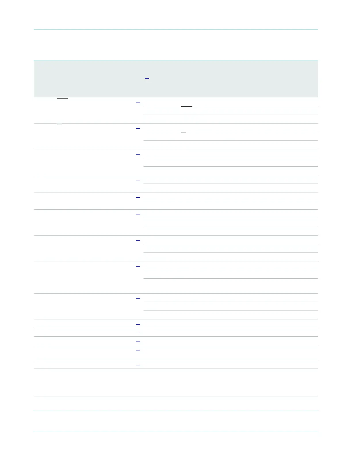
Table 134. LPC11U2x pin description
…continued
Symbol
Pin HVQFN33
Pin LQFP48
Pin LQFP64
Reset
state
[1]
Type Description

 Loading...


