OKI Data Infotech Corporation CONFIDENTIAL
Chapter 5 Troubleshooting (Engine Section and USB Controller Section)
5-101
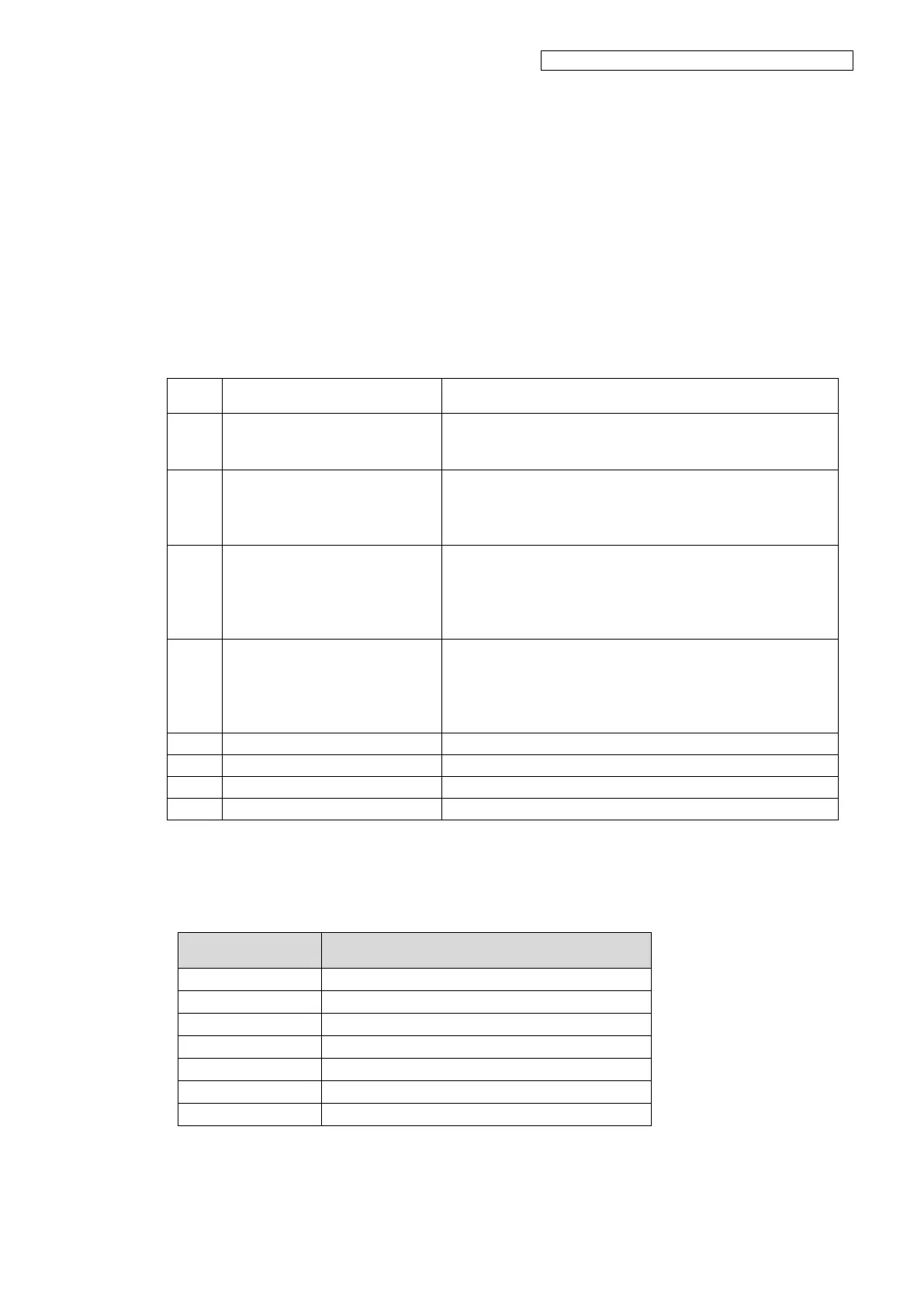
Case 1
An error between 1A00 and 1A08 has occurred.
<Action>
Check the Items to be Checked on the table below, and perform the actions starting from the top
until the problem is solved.
Note:
For this error occurs, be sure to perform the actions at the steps 1 to 4.
The width of the V-shaped folded
part on the
PCB-ASSY-HCB1M-side FFC
Check that the width of the V-shaped folded part on the FFC
is proper. If not, adjust it. For the adjustment procedure, see
6.8.4 PCB-ASSY-HCB1M.
Check the following to ensure that the FFC is not damaged.
- FFC’s terminal is detached from its base.
- FFC’s edges have not been abraded by friction.
If the FFC is damaged, replace it.
FFC’s connector connection
Reconnect the FFC on both the PCB-ASSY-HCB1M side and
the PCB-ASSY-IPB5-100 side.
If the cable terminals are smeared, softly wipe them with a
soft cloth or lint-free paper dampened with ethanol before
connecting them.
Robot cable’s connector
connection
Reconnect the robot cable on both the PCB-ASSY-HCB1M
side and PCB-ASSY-ACT3 side.
Before connecting, check that the connector terminals and
cable connection part are not disconnected. If a connection
failure is found, replace the robot cable.
Replace the PCB-ASSY-HCB1M.
Replace the PCB-ASSY-IPB5-100.
Case 2
An error between 1A0A and 1A19 has occurred.
Print head 1 and cable connected to print head 1
Print head 2 and cable connected to print head 2
Print head 3 and cable connected to print head 3
Print head 4 and cable connected to print head 4
Print head 5 and cable connected to print head 5
Print head 6 and cable connected to print head 6
Print head 7 and cable connected to print head 7