Home
Oki
Printer
IP-6620
Maintenance Manual
Page 472 (6.16.4 CASTER ASSY, MW, LCIS)
Oki IP-6620 - 6.16.4 CASTER ASSY, MW, LCIS
572 pages
Manual
Save Page as PDF
To Next Page
To Next Page
To Previous Page
To Previous Page
Loading...
OKI Data Infotech Corporation CONFIDENTIAL
Chapter 6 Parts Replacement (Disassembly/Reassembly)
6-
143
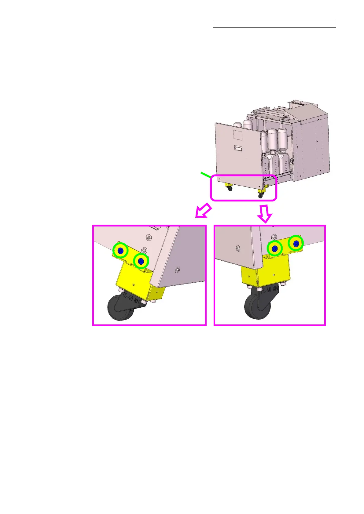
6.16.4
CA
STER A
SS
Y
, MW , LCIS
<Removal>
1.
Open the LCIS unit dra
wer
, and rem
ove
the two CASTER
ASSY
,MW,LCIS w
ith
four screws.
CASTER
ASSY
,MW,
LCIS
471
473
Table of Contents
Main Page
Chapter 1 Overview of Maintenance Workflow
15
1.1 Maintenance Workflow
15
1.2 Necessary Tools
16
1.3 External Views and Part Names (CIS model)
18
1.3.1 Front view
18
1.3.2 Rear view
19
1.3.3 Inner parts view
20
1.3.4 Printer heater section
21
1.3.5 Operation panel
22
1.3.6 Options
23
1.4 External Views and Part Names (LCIS model)
24
1.4.1 Front view
24
1.4.2 Rear view
25
1.4.3 Inner parts view
26
1.4.4 Printer heater section
27
1.4.5 Operation panel
28
1.4.6 Options
29
1.5 Maintenance Space
30
Chapter 2 Inspection and Maintenance
31
2.1 Periodic Inspection and Maintenance Guideline
31
2.1.1 How to check the daily maintenance execution rate
31
2.1.2 Regular inspection and maintenance operations
33
2.2 Maintenance when the Printer is Turned Off for more than One Month
34
2.3 Replacement of Parts
34
2.4 Cleaning
34
2.5 Cleaning of the Front Cover and Media Feed and Output Parts
35
2.6 Platen Cleaning
36
2.7 Print Head Cleaning
37
2.8 Changing the Printer Specifications from 6 Colors to 7 Colors (CIS)
39
2.9 Parts Requiring Periodic Replacement
40
Chapter 3 Maintenance Mode Functions and Operations
41
3.1 Introduction
41
3.2 Maintenance Mode Operations
42
3.2.1 On the operation panel
42
3.2.2 On CP_Manager
43
3.3 Basic Menu Operations
44
3.3.1 Menu tree
44
3.3.1.1 MENU button
45
3.3.1.2 ADJUST button
52
3.3.1.3 MAINTENANCE button
56
3.3.1.4 NOZZLE PRINT button
58
3.3.1.5 PH. RECOVERY button
58
3.4 Menu Operation
59
3.4.1 MENU
59
3.4.1.1 INFORMATION
59
3.4.1.2 SETTING
73
3.4.2 ADJUST
87
3.4.2.1 BIDIR POSITION
87
3.4.2.2 MECHANICAL ADJUST
89
3.4.2.3 PH VOLTAGE OFFSET
106
3.4.3 MAINTENANCE
107
3.4.3.1 PH MAINTENANCE
107
3.4.3.2 OTHER MAINTENANCE
117
3.4.3.3 COUNTERS
120
3.4.3.4 TEST PATTERNS
128
3.4.3.5 CHECK PATTERN
133
3.5 Special Operations
137
3.5.1 Language setting mode
138
3.5.2 Post-head replacement guidance skip mode
138
3.5.3 POC Skip Mode (Not available to users)
138
3.5.4 Ignore fatal error mode (Not available to users)
139
3.6 Special Operations' Guidance
140
3.6.1 Starting the printer with setting the language
140
3.6.2 Starting the printer with setting the number of color selection (CIS model only)
142
3.6.3 Starting the printer after replacing the print head
144
3.7 Management of System Information
146
3.8 CP_Manager <Maintenance Mode>
149
Chapter 4 Troubleshooting (General)
154
4.1 Items to Check when a Problem Occurs
154
Chapter 5 Troubleshooting (Engine Section and USB Controller Section)
160
5.1 Poor Print Quality
161
5.2 Error Message Types
174
5.3 Operator Call Error Messages
175
5.3.1 Ink-related messages
183
5.3.2 Waste ink bottle related messages
191
5.3.3 Media jam related messages
193
5.3.4 Media-related messages
196
5.3.5 Messages related to print heads
199
5.3.6 Communication-related messages
201
5.3.7 Others
202
5.4 Warning Messages
210
5.4.1 Cap open warning
214
5.4.2 Cap open warning (low)
214
5.4.3 The cleaning sheet has not been removed
214
5.4.4 Media wrinkles check
215
5.4.5 The bidirectional print position has not been adjusted
215
5.4.6 The media advance has not been adjusted
216
5.4.7 The start maintenance has not been performed
216
5.4.8 It is recommended to perform PH recovery
216
5.4.9 The print heads have not been cleaned
217
5.4.10 Sheet mount cleaning has not been performed
217
5.4.11 Some start maintenance operations have not been performed
218
5.4.12 The waste ink bottle is almost full
218
5.4.13 Ink is running low (CIS model)
219
5.4.14 The reservoir is almost empty. (LCIS model)
219
5.4.15 The subscription expiration date is close
220
5.4.16 The amount of ink that can be used is low. (LCIS model)
220
5.4.17 TUR unit operation timeout
221
5.4.18 The TUR unit is not installed properly
222
5.4.19 Remaining ink has almost run out
223
5.4.20 Wiper blade replacement
223
5.4.21 Wiper sponge replacement
223
5.4.22 Wiper cleaning liquid replacement
224
5.4.23 Part replacement
224
5.5 System Error Messages
226
5.5.1 System Error 100X: CPU Exception
237
5.5.2 System Error 11XX: Hardware Mismatch Error
238
5.5.3 System Error 1200: FPGA(ATG RSM) Load Error
238
5.5.4 System Error 130X/301X: CRG-FFC Connection Error
239
5.5.5 System Error 1310: FPGA(PTG) Load Error
241
5.5.6 System Error 1320: Data Transfer Error from FPGA-RSM to FPGA-PTG
242
5.5.7 System Error 1400: PCB-ASSY-ACT3 Connection Error
243
5.5.8 System Error 1410: FPGA(ABC) Load Error
244
5.5.9 System Error 1500: PCB-ASSY-TRC-MW Connection Error
245
5.5.10 System Error 1600: RSM Register Read/Write Error
246
5.5.11 System Error 1610: Flash Check Sum Error
247
5.5.12 System Error 1620: PCB-ASSY-IPB5-100 Initialization Error
247
5.5.13 System Error 1630: Band Memory Read/write Error
248
5.5.14 System Error 164X: USB Chip Register Read/write Error
249
5.5.15 System Error 1650: EEPROM Initialization Check Error
250
5.5.16 System Error 1660: RSM Mask Memory Read/write Error
250
5.5.17 System Error 1670: ATG Register Read/write Error
251
5.5.18 System Error 1700: ABC Register Read/write Error
252
5.5.19 System Error 1800: PTG Register R/W Error
253
5.5.20 System Error 190x: Power Supply Unit Error
254
5.5.21 System Error 1aXX: Carriage Power Error
259
5.5.22 System Error 1c0X: Thermistor Connection Error
262
5.5.23 System Error 1e00: Cap Correction Value Error
263
5.5.24 System Error 2010: Long-term Storage Error
264
5.5.25 System Error 203X: Periodic Part Replacement Error
265
5.5.26 System Error 2100: EEPROM I/O Error
266
5.5.27 System Error 2200: Data Path Time-out
266
5.5.28 System Error 2210: USB DMA Time-out
267
5.5.29 System Error 230X: Suction Fan Error
268
5.5.30 System Error 2310: Home Position Sensor Error
269
5.5.31 System Error 2320: Wiper Position Sensor Error
270
5.5.32 System Error 2330: Wiper Operation Error
273
5.5.33 System Error 2340: Capping Unit Sensor Error
274
5.5.34 System Error 235X: Remaining Ink Sensor Error (LCIS model)
275
5.5.35 System Error 2400: Environmental Temperature Thermistor Error
276
5.5.36 System Error 250X: Media Heater Thermistor Error
277
5.5.37 System Error 251X: Media Heater Error (High temperature)
278
5.5.38 System Error 252X: Media Heater Error (Target temperature not reached)
279
5.5.39 System Error 253X: Media Heater Error (No interrupt)
280
5.5.40 System Error 260X: Subtank Sensor Error
282
5.5.41 System Error 261x: Subtank Full Sensor Error
284
5.5.42 System Error 262x: Subtank Empty Sensor Error
286
5.5.43 System Error 270X: Ink Supply Pump Sensor Error
288
5.5.44 System Error 271X: Ink Supply Pump Error (LCIS model)
289
5.5.45 System Error 280X: Ink Usage Upper-limit Error
290
5.5.46 System Error 2900: Take-up Motor Overcurrent
291
5.5.47 System Error 2a0X: Servo Error
292
5.5.48 System Error 2b00: FIRE END Detection Error
294
5.5.49 System Error 2c0X: Ionizer Voltage Error
296
5.5.50 System Error 2d0X:Automatic Print Adjustment Calibration Error
297
5.5.51 System Error 3020: RSM-PTG FIFO Connection Error
298
5.5.52 System Error 3100: Edge Sensor Error
299
5.5.53 System Error 3140: Head Cooling Fan Error
300
5.5.54 System Error 320X: Head Drive Voltage Error
301
5.5.55 System Error 330X: No Head
303
5.5.56 System Error 340X: Head Information Error
305
5.5.57 System Error 350X: Head Thermistor Error
307
5.5.58 System Error 360X: Head Heater Error (High Temperature)
309
5.5.59 System Error 361X: Head Heater Error (Target Temperature Not Reached)
311
5.5.60 System Error 4XXX and 5XXX: Firmware Internal Error
313
5.6 If No Error Message Appears
314
5.6.1 Nothing is displayed
314
5.7 Updating the Firmware
315
5.7.1 Create an USB drive for updating the firmware
315
5.7.2 Updating with the USB drive
316
5.7.3 Online updating the firmware
322
5.8 Settings when Replacing the Engine Board (IPB5)
325
5.9 About the PCB-ASSY-IPB5-100 Board
328
5.9.1 Lithium battery problem
328
5.9.2 IC (EEPROM)
329
Chapter 6 Parts Replacement (Disassembly/Reassembly)
330
6.1 How to Read Disassembly/Reassembly Procedures
330
6.2 Part Names
331
6.2.1 Names and layout of parts
331
6.3 Disassembling and Reassembling Exterior Parts
332
6.3.1 COVER(FRONT)ASSY-MW
332
6.3.2 COVER(L)ASSY-MW, and COVER(R)ASSY-MW
333
6.3.3 COVER(Y-RAIL)-SL-MW, and COVER(Y-RAIL)-SR-MW
334
6.3.4 COVER(Y-RAIL)-64-MW
335
6.3.5 COVER(R-L)-MW
336
6.3.6 COVER(SIDE-L)-MW
337
6.3.7 COVER(SIDE-R)-MW
338
6.3.8 FAN(REAR)ASSY MW
339
6.3.9 OP-PANEL-UNIT-MW
340
6.3.10 COVER(PINCH-D)64-MW
341
6.3.11 COVER(SUBTANK)-MW
341
6.3.12 SWITCH(Interlock)-ASSY and SWITCH(COVER)-ASSY
342
6.3.13 Photo sensor LG248NL1
344
6.3.14 FAN(REAR)ASSY MW
345
6.3.15 CASE(CUTTER) and SLIDER(CUTTER)
346
6.4 Disassembling and Reassembling the Y Driver
347
6.4.1 Y DRIVE MOTOR and DRIVING PULLEY
347
6.4.2 BELT(SUS)
351
6.4.3 Y-TENSION-PULLEY
353
6.4.4 ROLLER(PINCH)
354
6.4.5 T-FENCE
356
6.4.6 ROBOT CABLE, MW
357
6.4.7 CARRIAGE FFC, MW
360
6.5 Disassembling and Reassembling the X Driver
363
6.5.1 X-MOTOR-ASSY (with PINION)
363
6.5.2 SUCTION FAN
367
6.5.3 PCB-ASSY-SNS1 (Front side)
368
6.5.4 PCB-ASSY-SNS1 (Rear side)
369
6.5.5 GRIT-UNIT
370
6.6 Disassembling and Reassembling the POWER BOX
373
6.6.1 FUSE
374
6.6.2 FAN(EL UNIT) ASSY MW (POWER-BOX)
376
6.6.3 POWER SUPPLY
377
6.6.4 PCB-ASSY-TRC(MW)
378
6.7 Disassembling and Reassembling the Controller Box
379
6.7.1 PCB-ASSY-IPB5-100 and PCB-ASSY-ACT3 boards
379
6.7.2 FAN(EL UNIT)ASSY MW Controller box
381
6.8 Disassembling and Reassembling the Print Head and the Carriage
382
6.8.1 Print head replacement
382
6.8.2 CABLE(HEAD)2-ASSY(MW)
389
6.8.3 PCB-ASSY-SNS1
391
6.8.4 PCB-ASSY-HCB1M
392
6.8.5 CASE-HEAD-MW-ASSY
395
6.8.6 LINEAR ENCODER ASSY(MW)
396
6.8.7 FAN(EL UNIT)ASSY MW
398
6.8.8 PCB-ASSY-ADJ1
399
6.8.9 FFC-ADJ
401
6.8.10 Ionizer
406
6.8.11 CAM-UD
409
6.9 Disassembling and Reassembling the WIPING-UNIT-MW
417
6.9.1 WIPING-UNIT-MW
417
6.9.2 WIPE-SW-ASSY-MW and SWITCH(HVSENSOR)ASSY
419
6.10 Disassembling and Reassembling the CAPPING-UNIT-MW
420
6.10.1 Opening and closing the caps manually
420
6.10.2 CAPPING-UNIT-MW
421
6.10.3 TORQUE-LIMITER
424
6.10.4 PUMP-F-ASSY (MW) and Damper O-ring
425
6.10.5 CAP-ASSY(MW)
427
6.10.6 SWITCH(CAP)-ASSY and LEVER(CAP)-ASSY
432
6.10.7 SOLENOID ASSY(MV)
433
6.10.8 MOTOR(CAPPING)-ASSY
434
6.11 Disassembling and Reassembling the WASTE-BOTTLE-UNIT
435
6.11.1 WASTE INK BOTTLE TRAY AND TUBE, MW
435
6.11.2 MICRO SWITCH 4(WASTE INK BOTTLE ASSY)
437
6.12 Disassembling and Reassembling the INKBOX-UNIT
439
6.12.1 INKBOX-UNIT-MW
439
6.12.2 INKBOX COVER(HV)
440
6.12.3 INKBOX FACE(HV)
440
6.12.4 COVER(INKBOX-REAR)-MW
440
6.12.5 SUPPLYPUMP-UNIT(MW)
441
6.12.6 SUPPLY-PUMP-TUBE-ASSY
442
6.12.7 PCB-ASSY-INK4
443
6.12.8 PHOTO SENSOR 5
444
6.12.9 O-RING
445
6.13 Disassembling and Reassembling the SUBTANK-UNIT
446
6.13.1 NEEDLE-FIX-PLATE-FRONT-ASSY
446
6.13.2 SubtankSensors(OKI Data Infotech) and Actuator Photo Interrupter
447
6.13.3 SUBTANK-ASSY(MW)
448
6.14 Disassembling and Reassembling the Heater Section
449
6.14.1 PAPER-GUIDE-DELIVERY64-MW-ASSY (with heater)
449
6.14.2 PAPER-GUIDE-FEEDING64-MW-ASSY (with heater)
451
6.14.3 PLATEN64-MW-ASSY
452
6.14.4 EDGE-GUARD-SET(L)-MW and EDGE-GUARD-SET(R)-MW
455
6.15 Disassembling and Reassembling the TAKE UP REEL UNIT and FEEDING-UNIT
456
6.15.1 FLANGE(2-INCH)
456
6.15.2 MOTOR-UNIT
457
6.15.3 CABLE(TU-Switch)-ASSY
459
6.15.4 Torque limiter and TUR EM clutch
460
6.15.5 PHOTO-IC-ASSY
462
6.15.6 SWITCH(RollEnd)-ASSY
464
6.15.7 TUR slide switch
465
6.15.8 TORQUE LIMITER 1500C
466
6.16 Disassembling and Reassembling the LCIS-UNIT
467
6.16.1 SUPPLY PUMP, MW, LCIS
467
6.16.2 SUPPLY PUMP TUBE, MW, LCIS
469
6.16.3 REMAINING INK SENSOR, MW, LCIS
470
6.16.4 CASTER ASSY, MW , LCIS
472
6.16.5 FILTER ASSY, MW, LCIS
473
Chapter 7 Adjustment
476
7.1 Adjustment of CARRIAGE-UNIT-MW Height
477
7.2 SUS-BELT Tension Adjustment
482
7.3 TIMING-BELT-Y Tension Adjustment
484
7.4 Correcting the Cap Position
487
7.5 Wiping Position Adjustment
489
7.5.1 Wiping unit adjustment
489
7.5.2 Single color adjustment
497
7.6 Print Head Inclination Adjustment
502
7.7 Wiping Height Adjustment
504
7.8 PLATE(CARRIAGE-CAP)-MW Adjustment
505
7.9 REMAINING INK SENSOR, MW, LCIS Adjustment
506
7.10 Linear encoder position adjustment
514
Chapter 8 Operation Mechanism
522
8.1 Overview of System Operation Mechanism
522
8.2 Carriage System
527
8.3 Ink Delivery System
529
8.4 Various Functions for Printing
534
8.5 Head Driving Principle
539
8.6 Print Modes
541
8.7 Electrical Configuration
542
8.7.1 Overall configuration
542
8.8 Description of the Electrical Section
543
8.9 Engine Control Firmware
552
8.9.1 Function block
552
8.9.2 Performance description
553
8.10 Power Supply Unit
554
8.10.1 Electric specifications
554
8.10.2 Connector specifications
555
8.10.3 DC power supply configuration
556
8.10.4 When the interlock is disconnected
558
8.10.5 Power output voltage variability
559
8.10.6 Protection circuit
560
8.11 Media Heater Section
561
8.11.1 Configuration
561
8.11.2 Block diagram
562
Appendix IP-6620 Wiring Diagram
563
Other manuals for Oki IP-6620
User Guide
280 pages
Quick Reference Guide
250 pages
Related product manuals
Oki IP-5620
141 pages
Oki B4100
90 pages
Oki B2200
35 pages
Oki B410D
84 pages
Oki ES7411
76 pages
Oki ES6410
76 pages
Oki B6300 Series
70 pages
Oki B4400 Series
104 pages
Oki B6500 Series
28 pages
Oki B4000 Series
6 pages
Oki Microline 320
29 pages
Oki Microline 520
68 pages