OKI Data Infotech Corporation CONFIDENTIAL
Chapter 5 Troubleshooting (Engine Section and USB Controller Section)
5-140
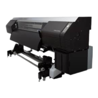
5.5.52 System Error 3100: Edge Sensor Error
<Description>
Though the edge sensor’s sensitivity was adjusted, the output voltage is not within the expected
range.
<Faulty part>
(1) Media detect and Line sensor OKI Data Infotech
(2) PCB-ASSY-HCB1M
(3) Carriage cable (FFC): CARRIAGE FFC, MW
(4) Robot cable: ROBOT CABLE, MW
<Action>
Check the Items to be Checked on the table below, and perform the actions starting from the top
until the problem is solved.
Non-reflecting tape condition on
the platen
Check that the tape is not smeared. If it is, softly wipe it with
a soft cloth or lint-free paper moistened with wiper cleaning
liquid or cap cleaning liquid.
Check that the harness connector condition is proper as
follows.
- The connectors are connected securely.
- The cable is not disconnected.
- The harness is not pinched by other parts.
- The cable jacket is not damaged.
Check that the sensor is fixed securely.
Remove the sensor, softly wipe it with a soft cloth or lint-free
paper moistened with ethanol, and re-connect it.
If the error persists, replace the sensor.
The width of the V-shaped folded
part on the
PCB-ASSY-HCB1M-side FFC
Check that the width of the V-shaped folded part on the FFC
is proper. If not, adjust it. For the adjustment procedure, see
6.8.4 PCB-ASSY-HCB1M.
Check the following to ensure that the FFC is not damaged.
- FFC’s terminal is detached from its base.
- FFC’s edges have not been abraded by friction.
If the FFC is damaged, replace it.
FFC’s connector connection
Reconnect the FFC on both the PCB-ASSY-HCB1M side
and the PCB-ASSY-IPB5-100 side.
If the cable terminals are smeared, softly wipe them with a
soft cloth or lint-free paper dampened with ethanol before
connecting them.
Robot cable’s connector
connection
Reconnect the robot cable on both the PCB-ASSY-HCB1M
side and PCB-ASSY-ACT3 side.
Before connecting, check that the connector terminals and
cable connection part are not disconnected. If a connection
failure is found, replace the robot cable.
Replace the PCB-ASSY-HCB1M.