OKI Data Infotech Corporation CONFIDENTIAL
Chapter 6 Parts Replacement (Disassembly/Reassembly)
6-71
Note
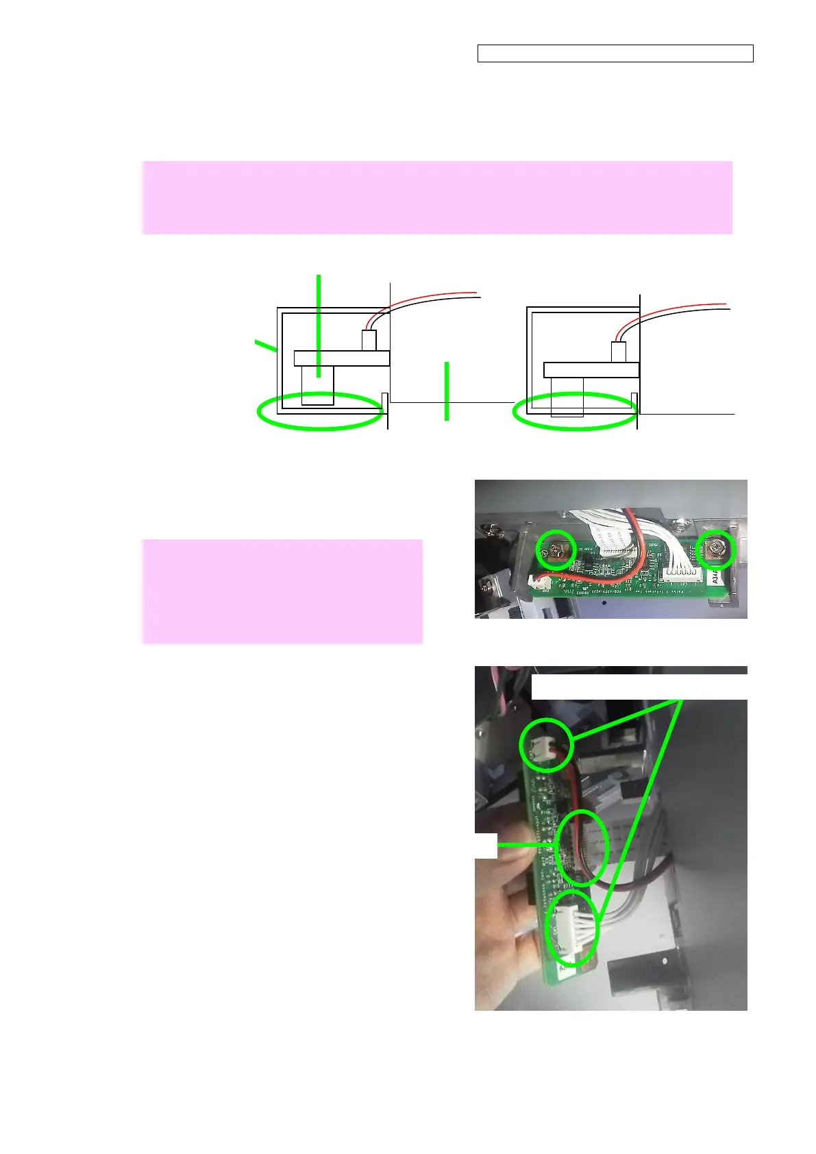
The figure below shows the correct ADJ1-COVER-ASSY installation.
When installing the ADJ1-COVER-ASSY, check that the bottom surface of the
ADJ1-COVER-ASSY is lower than the PCB-ASSY-ADJ1's sensor.
4. Remove the PCB-ASSY-ADJ1 and two
fixing screws.
Note
With the PCB-ASSY-ADJ1, do not disconnect
or connect the connector. Connecting or
disconnecting the connector may apply too
much stress to the PCB-ASSY-ADJ1 and
damage it.
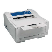
5. From the PCB-ASSY-ADJ1, disconnect
the following.
- CABLE(ADJ-AD)-ASSY's two
connectors
- FFC-ADJ's connector.
Connector for CABLE(ADJ-AD)-ASSY