17. Malfunction code Field Service Ver. 1.0 Jun. 2008
300
Troubleshooting
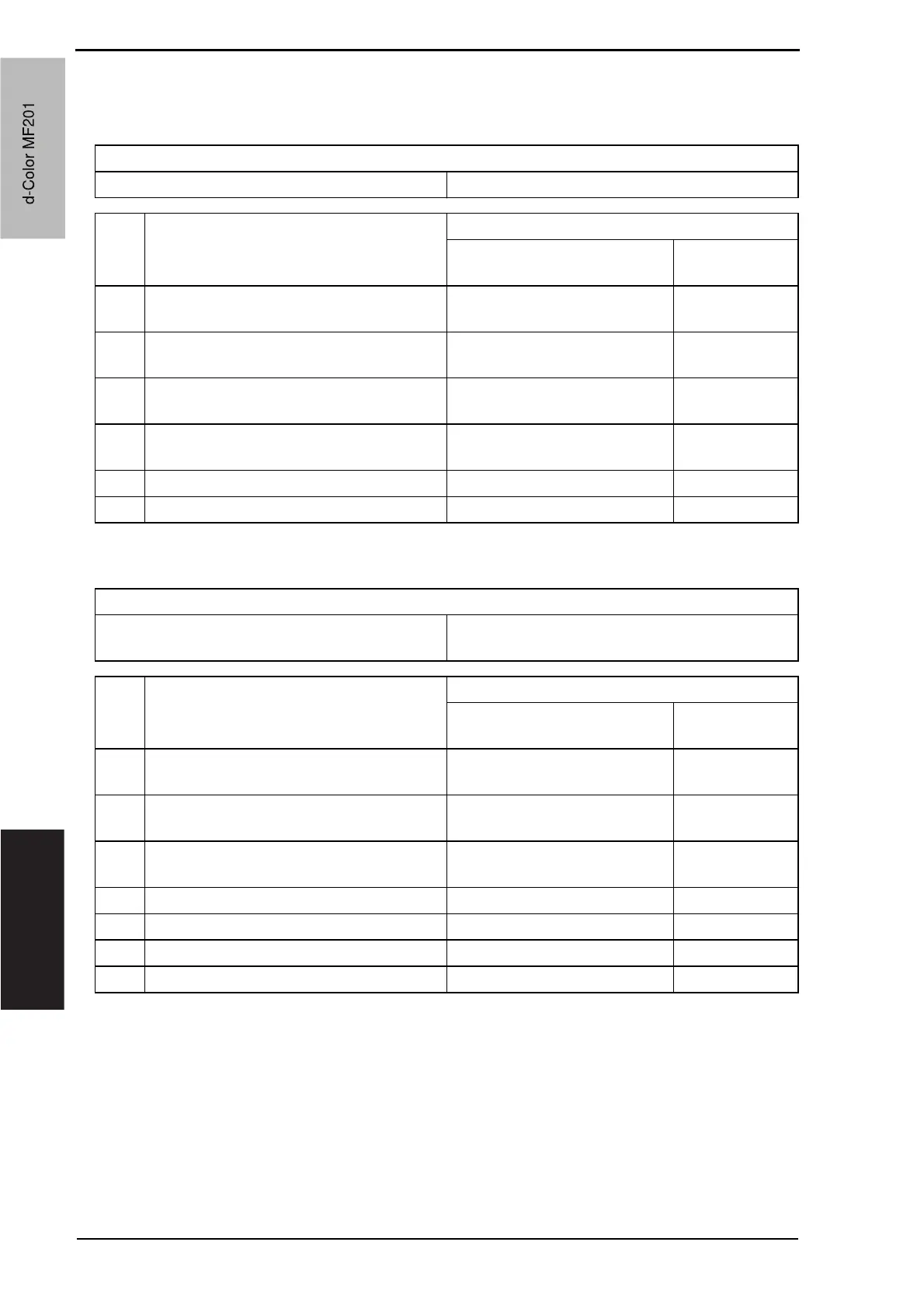
17.5.5 C2253: Color PC motor’s failure to turn
17.5.6 C2254: Color PC motor’s turning at abnormal timing
17.5.7 C225D: Color dev. unit engagement/disengagement failure
Relevant parts
Color PC motor (M3) Printer control board (PRCB)
Step Action
WIRING DIAGRAM
Control signal
Location (Electri-
cal component)
1
Check the M3 connector for proper
connection and correct as necessary.
——
2
Check the M3 connector for proper drive
coupling and correct as necessary.
——
3
Check the PRCB connector for proper
connection and correct as necessary.
——
4 M3 operation check
PRCB CN28-9 (REM)
PRCB CN28-11 (LOCK)
C to D-23 to 24
5 Change M2 — —
6 Change PRCB — —
Relevant parts
Color dev. unit engaged motor (M4)
Color dev. unit engaged position sensor (PS19)
Printer control board (PRCB)
Step Action
WIRING DIAGRAM
Control signal
Location (Electri-
cal component)
1
Check the M4 connector for proper
connection and correct as necessary.
——
2
Check the M4 connector for proper drive
coupling and correct as necessary.
——
3
Check the PRCB connector for proper
connection and correct as necessary.
——
4 PS19 I/O check, sensor check PRCB CN33-18 (ON) C to D-10
5 M4 operation check PRCB CN33-20 (REM) C to D-10
6 Change M4 — —
7 Change PRCB — —
d-Color MF201
Service Manual Y109660-1
d-Color MF201
 Loading...