19. Image quality problem Field Service Ver. 1.0 Jun. 2008
318
Troubleshooting
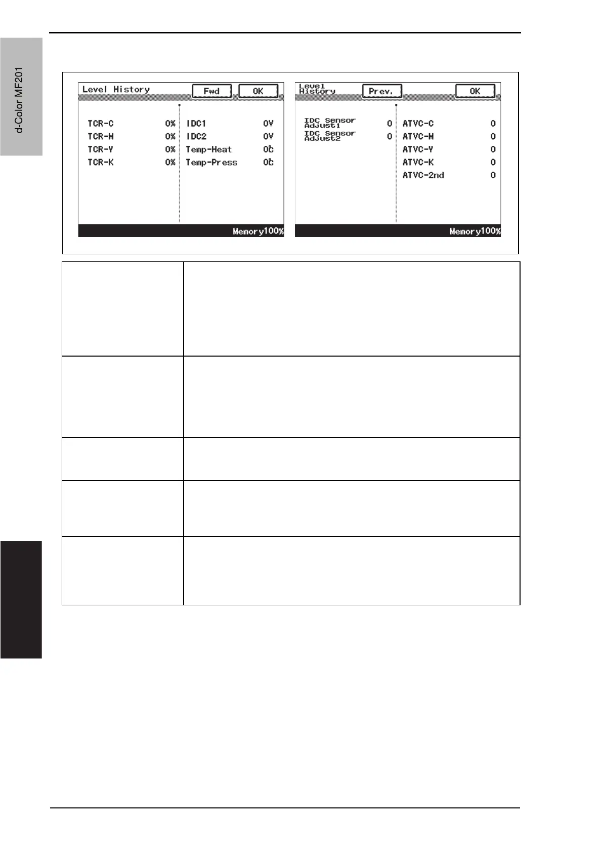
19.1.2 Level history
TCR-C
TCR-M
TCR-Y
TCR-K
• Shows the T/C ratio reading taken last (in 0.01 % increments).
• Standard value: 6 to 8 %
• Relevant components: TCR sensor
• “Reading taken last” means:
Latest value
When the Start key is pressed, the output value is displayed while a test
print is being produced.
IDC1
IDC2
• Shows the IDC bare surface output reading taken last (in 0.01 V incre-
ments).
• It should normally be around 4.3 V.
• The output range is 0 V to 5 V.
• “Reading taken last” means: Present value
• Relevant components: IDC sensor, transfer belt unit
Temp-Heat
Temp-Press
• Shows the temperature of the each part of the fusing unit
(in 1 qC increments).
• Relevant components: Fusing unit
IDC Sensor Adjust 1
IDC Sensor Adjust 2
• Shows the IDC intensity adjustment value.
• It should normally be around 40 and can range from 0 to 255.
• The value becomes greater as the transfer belt unit has been used more.
• Relevant components: IDC sensor, transfer belt unit
ATV C - C
ATV C - M
ATV C - Y
ATV C - K
ATVC -2nd
• Shows the latest ATVC level (which varies according to the paper type).
•5 PA to 40 PA (ATVC-C/-M/-Y/-K)
• 300 V to 4800 V (ATVC-2nd)
• Relevant components: Transfer belt unit, High voltage unit (HV),
2nd transfer assy
A02FF4E517DA
d-Color MF201
Service Manual Y109660-1
d-Color MF201
 Loading...