Home
Olivetti
All in One Printer
d-Color MF201
Olivetti d-Color MF201 Service Manual
4
of 1
of 1 rating
396 pages
Give review
Manual
Specs
To Next Page
To Next Page
To Previous Page
To Previous Page
Loading...
Field Ser
vice V
er
. 1.0 J
un. 2008
6. Other
73
Maintenance
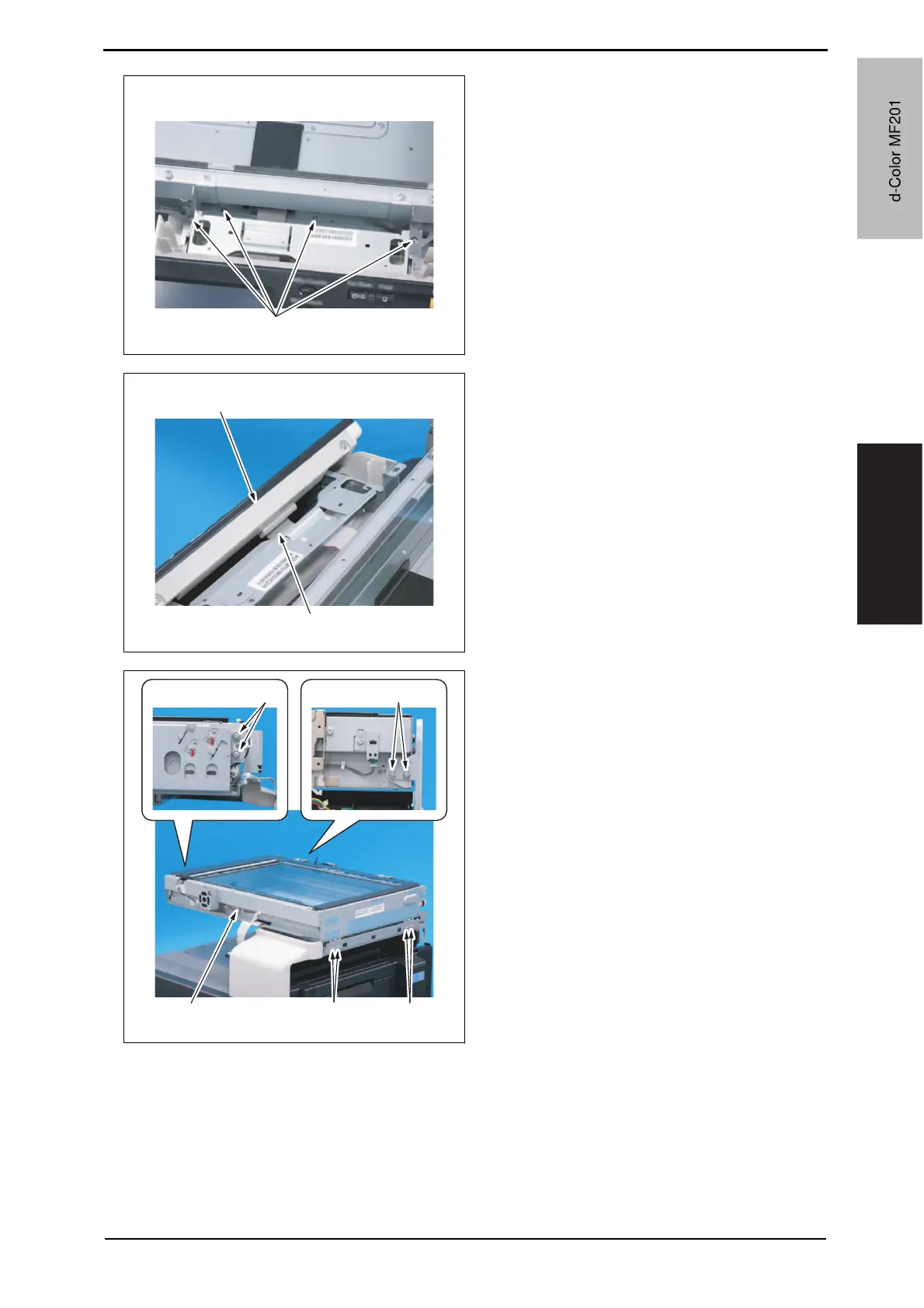
11.
Remo
v
e four scre
ws [1].
12.
Disconnect the connector [1], and
remov
e the control panel assy [2].
13.
Remo
v
e eight screws [1], and
remov
e the scanner chassis [2].
A02FF2C113D
A
[1]
A02FF2C114D
A
[1]
[2]
A02FF2C115D
A
[1]
[1]
[1]
[1]
[2]
d
-
Color
M
F
201
Y109660-1
Sevice
Manual
d
-
C
o
l
o
r
M
F
2
0
1
87
89
Table of Contents
Default Chapter
3
Revision History
3
Table of Contents
4
Outline
16
1 System Configuration
16
Field Service Ver. 1.0 Jun
16
2 Product Specifications
18
Maintenance
24
3 Periodical Check
24
Maintenance Items
24
Main Body
24
Df-612
25
Maintenance Parts
26
Replacement Parts
26
Cleaning Parts
27
Concept of Parts Life
28
Life Value of Consumables and Parts
28
Conditions for Life Specifications Values
29
Control Causing Inhibited Printing for One Part When an Inhibited-Printing Event Occurs in Another Part
29
Cleaning of the Area Around the Waste Toner Collecting Port
30
Cleaning of the Timing Roller
30
Maintenance Procedure (Periodical Check Parts)
30
Replacing the Waste Toner Box
31
Replacing the Transfer Roller Unit
32
Replacing the Imaging Unit
33
Replacing the Ozone Filter
37
Replacing the Toner Cartridge
37
Replacing the Transfer Belt Unit
39
Cleaning of the IDC/Registration Sensor/Mk,Yc
41
Cleaning of the Image Transfer Entrance Guide
41
Cleaning of the Original Glass Assy
42
Cleaning of the each Mirror and the Lens
43
Cleaning of the Exposure Lamp
43
4 Service Tool
44
Service Material List
44
CE Tool List
44
Copy Materials
45
Field Service Ver. 1.0 Jun
45
Imaging Unit Single Parts (IU)
45
Maintenance Kit
45
Toner Cartridge Single Parts (T/C)
45
Waste Toner Box
45
5 Firmware Upgrade
46
Preparations for Firmware Rewriting
46
Items Required
46
Writing Data to Compact Flash
46
Checking Version
46
Firmware Rewriting Procedures
47
Controller
47
Engine/Job Separator
48
6 Other
52
Disassembly/Adjustment Prohibited Items
52
Disassembly/Assembly/Cleaning List (Other Parts)
53
Disassembly/Assembly Parts List
53
Cleaning Parts List
54
Disassembly/Assembly Procedure
55
Front Door
55
Upper Front Cover
56
Right Front Cover
56
Left Cover
57
Left Shield Cover
57
Rear Left Cover
58
Exit Cover
58
IR Rear Cover
59
Paper Exit Rear Cover
59
Rear Cover
60
Rear Right Cover
60
Control Panel Assy
61
Exit Tray
62
Tray 1
62
Front Cover
63
IR Upper Front Cover
65
IR Left Cover
65
IR Right Cover
66
Original Glass Assy
66
ADF Glass Assy
67
Tray 1 Feed Roller
67
Tray 1 Separation Roller Assy
68
Fusing Unit
69
PH Unit
70
Main Drive Unit
75
Transport Drive Unit
78
Fusing Drive Unit
82
Hopper Drive Unit (C/K, Y/M)
84
Right Door Assy
85
Scanner Chassis
86
Exposure Unit
89
Flat Cable of the Exposure Unit
92
PH Relay Board (REYBPH)
94
DC Power Supply (DCPU)
96
Printer Control Board (PRCB)
97
Service EEPROM Board (SVERB)
98
High Voltage Unit (HV)
100
Tray 1 FD Paper Size Detect Board (PSDTB/1)
100
ADCU Board (ADCUB)
101
MFBU Board (MFBUB)
102
BCRU Board (BCRUB)
104
Inverter Board (INVB)
105
Transport Motor (M1)
106
Color PC Motor (M3)
107
Fusing Motor (M2)
107
Fusing Pressure Roller Retraction Motor (M12)
108
Toner Supply Motor/Ck (M7)
108
Scanner Motor (M201)
109
Toner Supply Motor/Ym (M6)
109
Transfer Belt Pressure Retraction Clutch (CL3)
110
Developing Clutch/K (CL4)
111
IDC Registration Sensor/Mk (IDCS/MK), IDC Registration Sensor/Yc (IDCS/YC)
112
Tim. Roller Clutch (CL1)
112
Exposure Lamp (FL201)
115
Scanner Drive Wires
117
Cleaning Procedure
122
Transfer Belt Unit
122
PH Window Y,M,C,K
122
Tray 1 Feed Roller
123
Tray 1 Separation Roller
123
Field Service Ver. 1.0 Jun
123
Mount the Original Size Detection Sensor/2 (PS204)
124
Adjustment/Setting
126
7 How to Use the Adjustment Section
126
8 Utility Mode
127
Utility Mode Function Tree
127
Utility Mode Function Setting Procedure
131
Procedure
131
Exiting
131
Changing the Setting Value in Utility Mode Functions
131
User Settings
132
System Settings
132
Display Settings
133
Default Settings
134
Copier Settings
135
Printer Settings
136
User Management
139
Confirmation Beep
139
Alarm Volume
139
Line Monitor Sound
139
Job Complete Beep
139
Panel Cleaning
139
Dehumidify
139
Pop3 Rx
140
Memory RX ON/OFF
140
One-Touch/Box Reg
140
One-Touch
140
Index
140
Domain Name
140
Bulletin
140
Admin. (Administrator Management)
141
System Settings
141
Administrator Settings
147
Account Track
148
Document Management
149
Fax Settings
149
Field Service Ver. 1.0 Jun
149
Print Lists
149
Printer Settings
149
Report Settings
149
RX Settings
149
TX Settings
149
Network Settings
150
Software Switch Setting
156
Firmware Version
158
Ping
158
Security Settings
158
9 Adjustment Item List
159
10 Service Mode
161
10.1 Service Mode Function Setting Procedure
161
10.2 Service Mode Function Tree
162
10.3 Machine Adjustment
165
Fusing Temperature
165
Fusing Transport Speed
166
Printer Area
167
Scan Area
171
Printer Resist Loop
176
Color Reg. Adjustment
177
Lead Edge Erase Adjustment
178
Manual Bypass Tray Adjustment
178
Touch Panel Adjustment
178
10.4 Imaging Process Adjustment
179
Gradation Adjust
179
Background Voltage Margin
180
D Max Density
180
Transfer Output Fine Adjustment
181
Image Stabilization
182
Thick Paper Density Adjustment
182
Dev. Bias Choice
183
Monochrome Density Adjustment
183
Toner Supply
183
10.5 System Input
184
Marketing Area
184
Exhaust Fan Stop Delay
184
Serial Number
185
No Sleep
185
Foolscap Size Setting
185
Install Date
185
Field Service Ver. 1.0 Jun
185
Change Fixed Zoom
186
File Display
186
Memory Clear
186
Software Switch Setting
188
Consumable Life Reminder
266
Unit Change
266
Option Settings
266
Center Erase Width
267
IU Life Setting
267
Counter
268
Life
268
Procedure
268
Jam
269
Maintenance
269
Service Call Counter
269
Service Total
269
Warning
269
ADF Paper
270
Fax Connection Error
270
Paper Jam History
270
Service Call History (Data)
270
List Output
270
Protocol Trace
270
Service Call Report
270
File Dump
271
State Confirmation
271
Sensor Check
271
Sensor Check Screens
272
Sensor Check List
273
Level History
277
Table Number
277
Temp. & Humidity
277
Color Regist
278
Field Service Ver. 1.0 Jun
279
Halftone Pattern
280
Color Reproduction
281
Security Settings
282
Settings in the Security Settings
283
12 Billing Setting
284
Settings in the Billing Setting
285
13 Procedure for Resetting
286
14 Initial Mode
287
Initial Mode Function Tree
288
Touch Panel Adj
289
15 Mechanical Adjustment
290
Field Service Ver. 1.0 Jun
291
16 Jam Display
292
Misfeed Display Resetting Procedure
293
Sensor Layout
294
Solution
295
Misfeed at Tray 1 Feed Section
296
Misfeed at 2Nd Image Transfer Section
297
Misfeed at Exit Section
298
Controller Jam
299
17 Malfunction Code
300
Solution
301
P-6: Cyan Imaging Unit Failure
302
P-12: Black PC Drive Sensor Malfunction
303
P-27: Secondary Transfer ATVC Failure
304
Trouble Code
305
How to Reset
312
Solution
313
C2152: Transfer Belt Pressure Welding Alienation
314
C2253: Color PC Motor's Failure to Turn
315
C2451: Release New Transfer Belt Unit
316
C2552: Abnormally High Toner Density Detected Cyan TCR Sensor
317
C2558: Abnormally High Toner Density Detected Black TCR Sensor
318
C2650: Main Backup Media Access Error
319
C2651: EEPROM Access Error (IU C)
320
C3101: Fusing Roller Separation Failure
321
C3301: Fusing Cooling Fan Motor/ 1 Failure to Turn
322
C3421: Fusing Heaters Trouble (Heating Side)
323
C3821: Fusing Abnormally Low Temperature Detection (Heating Side)
324
Field Service Ver. 1.0 Jun
325
C5351: Power Supply Cooling Fan Motor's Failure to Turn
326
C5357: Cooling Fan Motor/1'S Failure to Turn
327
C6401: Other Troubles of Scanner
328
C6751: CCD Clamp/Gain Adjustment Failure
329
18 Power Supply Trouble
330
Fusing Heaters Do Not Operate
331
19 Image Quality Problem
332
Level History
333
How to Identify Problematic Part
334
Solution
336
Scan Direction, Colored Lines in Main Scan Direction, and Colored Bands in Main Scan Direction
338
Scanner System: Color Spots
339
Scanner System: Fog
340
Scanner System: Blurred Image, Blotchy Image
341
Scanner System: Incorrect Color Image Registration, Sync Shift (Lines in Main Scan Direction)
342
Scanner System: Moire
343
Scanner System: Skewed Image
344
Scanner System: Distorted Image
345
Scanner System: Low Image Density, Rough Image
346
Scanner System: Defective ACS
347
Scanner System: Blank Copy, Black Copy
348
Scanner System: Abnormal Image
349
Scanner System: Uneven Density
350
Printer Monocolor: White Lines in Sub Scan Direction, White Bands in Sub Scan Direction, Colored Lines Colored Bands in Sub Scan Direction
351
Scan Direction, Colored Lines in Main Scan Direction, Colored Bands in Main Scan Direction
352
Printer Monocolor: Uneven Density in Sub Scan Direction
353
Printer Monocolor: Uneven Density in Main Scan Direction
354
Printer Monocolor: Low Image Density
355
Printer Monocolor: Gradation Reproduction Failure
357
Printer Monocolor: Foggy Background
358
Printer Monocolor: Void Areas, White Spots
360
Printer Monocolor: Colored Spots
361
Printer Monocolor: Blurred Image
362
Printer Monocolor: Blank Copy, Black Copy
363
Printer Monocolor: Uneven Image
364
Direction, Colored Lines in Sub Scan Direction, and Colored Bands in Sub Scan Direction
365
Direction, Colored Lines in Main Scan Direction, and Colored Bands in Main Scan Direction
366
Printer 4-Color: Uneven Density in Sub Scan Direction
367
Printer 4-Color: Uneven Density in Main Scan Direction
368
Printer 4-Color: Low Image Density
369
Printer 4-Color: Poor Color Reproduction
370
Printer 4-Color: Incorrect Color Image Registration
371
Printer 4-Color: Void Areas, White Spots
372
Printer 4-Color: Colored Spots
373
Printer 4-Color: Poor Fusing Performance, Offset
374
Field Service Ver. 1.0 Jun
375
Printer 4-Color: Back Marking
376
Printer 4-Color: Uneven Image
377
Appendix Parts Layout Drawing
378
Engine Section
379
Tray 1
383
DF-612 (Option)
384
MB-502 (Option)
385
PC-105 (Option)
386
PC-104/204 (Option)
387
PC-405 (Option)
388
Ad-505
389
JS-505 (Option)
390
21 Connector Layout Drawing
391
22 Timing Chart
392
Df-612
393
Sided Mode (A4 Three Sheets Feeding)
394
Other manuals for Olivetti d-Color MF201
Quick Guide
205 pages
Manual
69 pages
4
Based on 1 rating
Ask a question
Give review
Questions and Answers:
Need help?
Do you have a question about the Olivetti d-Color MF201 and is the answer not in the manual?
Ask a question
Olivetti d-Color MF201 Specifications
General
Brand
Olivetti
Model
d-Color MF201
Category
All in One Printer
Language
English
Related product manuals
Olivetti d-Color MF222
501 pages
Olivetti d-COLOR MF254
210 pages
Olivetti d-Color MF920
248 pages
Olivetti d-color MF451
321 pages
Olivetti d-color MF551
305 pages
Olivetti d-COLOR MF654
210 pages
Olivetti d-Color MF552
501 pages
Olivetti d-Color MF364
210 pages
Olivetti d-COLOR MF3300
163 pages
Olivetti d-Copia 3000MF
230 pages
Olivetti d-COPIA 3004MF
180 pages
Olivetti d-COPIA 3013MFplus
483 pages
 Loading...