6. Other Field Service Ver. 1.0 Jun. 2008
84
Maintenance
4. Enter the Service mode. Make individual adjustments shown in the following table in
the order listed, using the machine maintenance list and the adjustment lists that were
output at the time of main body installation and maintenance.
NOTE
• At this time, a front door must be an open state.
NOTE
• After replacing the service EEPROM board, be sure to make the above listed
adjustments before the first warm-up is made.
5. Turn OFF the main power switch and sub power switch.
6. Close the front door and turn ON the main power switch and sub power switch.
Check to see that warm-up and image stabilization operations are completed normally.
7. Enter the Service mode again. Make individual adjustments shown in the following
table in the order listed, using the machine management list and the adjustment lists
that were output at the time of main body installation and maintenance.
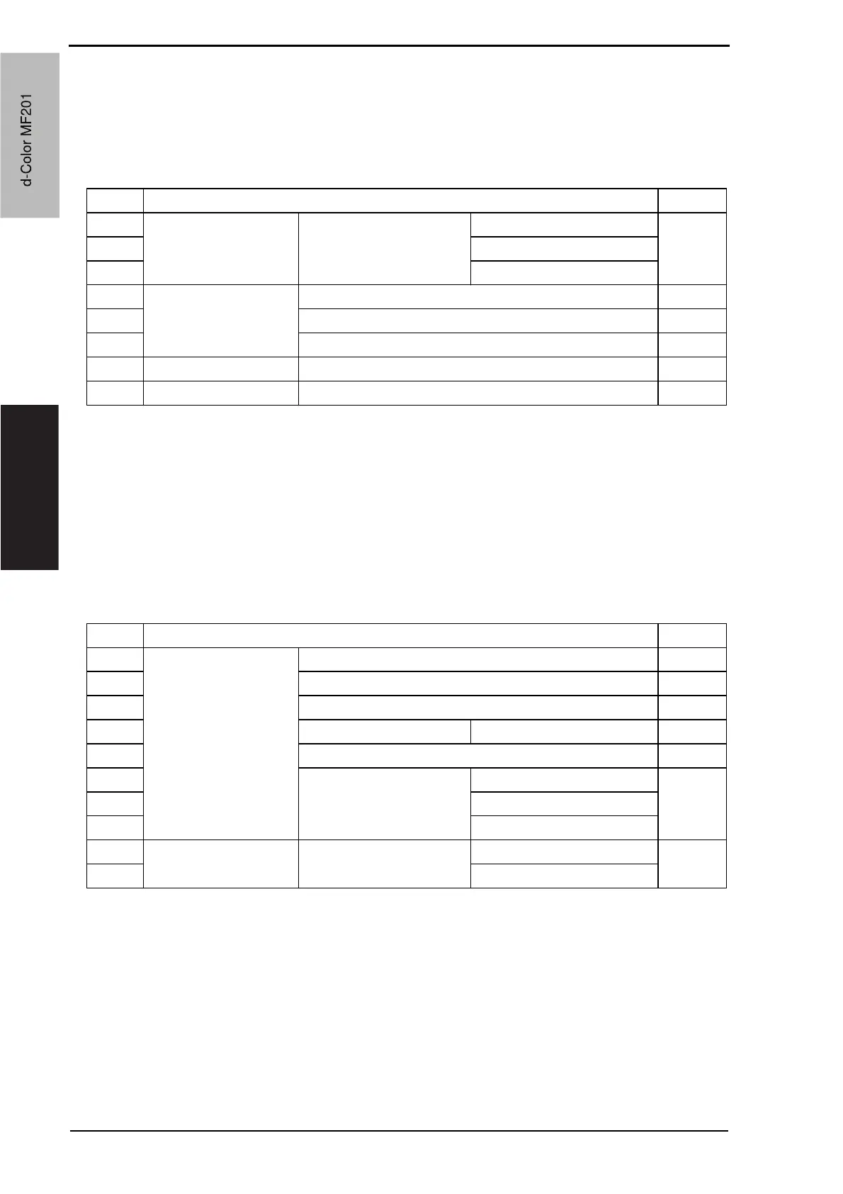
Order Items that require readjustment in the Service mode Ref. page
1 Machine Color Reg. Adjustment Cyan P.162
2 Magenta
3 Yellow
4 Imaging Process
Adjustment
Background Voltage Margin P.165
5 D Max Density P.165
6 Dev. Bias Choice P.168
7 Machine Exhaust Fan Stop Delay P.169
8 System IU Life Setting P.252
Order Items that require readjustment in the Service mode Ref. page
1 Machine Manual Bypass Tray Adjustment P.163
2 Printer Resist Loop P.161
3 Fusing Temperature P.150
4 Printer Area Paper Feed Direction Adj. P.152
5 Fusing Transport Speed P.151
6 Printer Area Centering P.152
7 Centering (Duplex 2nd Side)
8 Leading Edge Adjustment
9 Imaging Process
Adjustment
Transfer Output Fine
Adjustment
Secondary transfer adj. P.166
10 Primary transfer adj.
d-Color MF201
Service Manual Y109660-1
d-Color MF201
 Loading...