2.18 Configurable Connectors
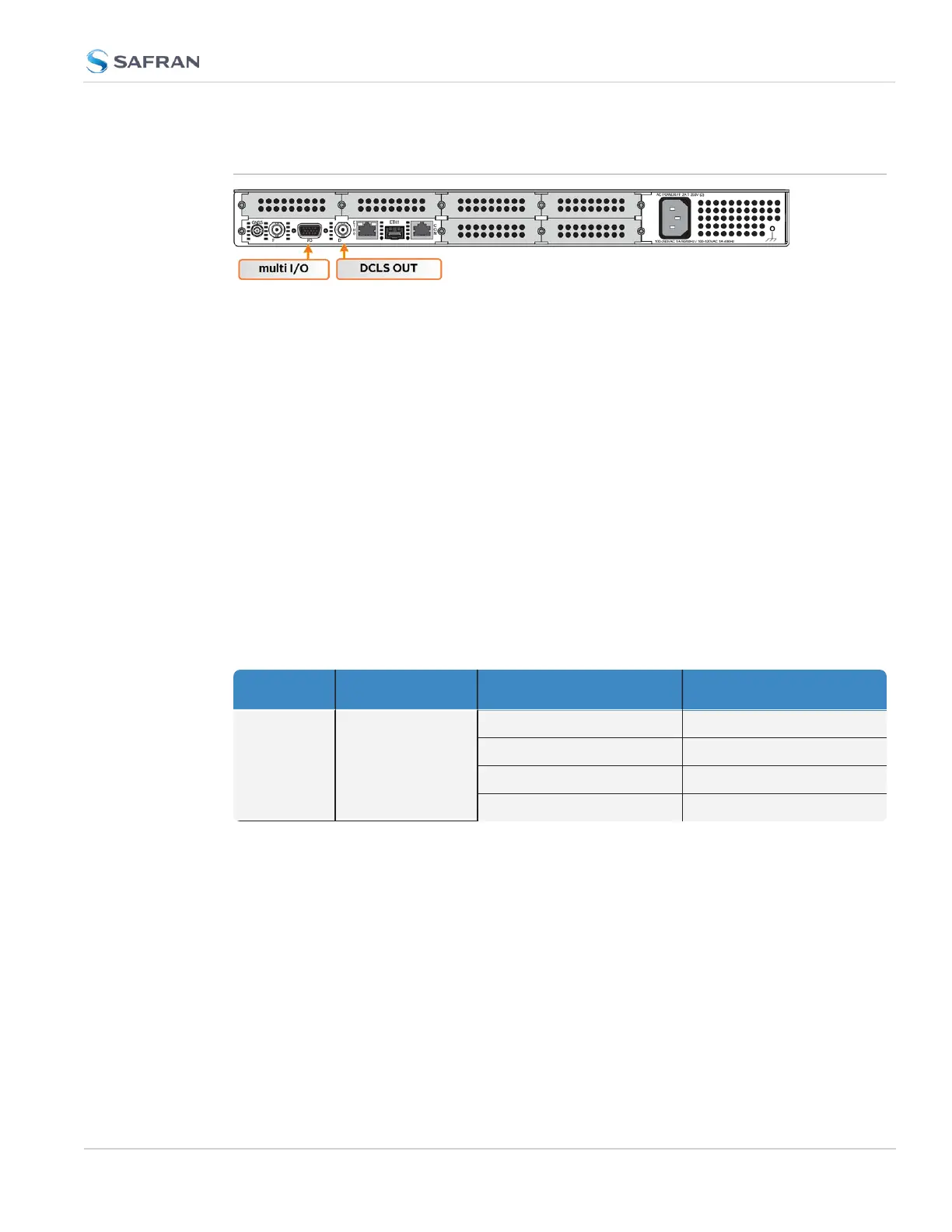
This Section covers the two software-configurable connectors on the CPU board
(rear panel): the BNC DCLS OUT connector and the HD15 multi I/O connector.
When you configure an input our output via the DCLS OUT connector or the I/O
connector, you will need to adjust both the pin configuration ("Assigning Signals"
on page160) and (for some types) the settings for that input or output via the
Web UI ("Configuring Input References" on page161 and "Configuring Outputs"
on page169).
You can find the settings for signals currently configured through these two con-
nectors under INTERFACES > OPTION CARDS > Main. The CPU board with the
standard-issue connectors is referred to as "Option Card 0" in the Web UI.
2.18.1 BNC DCLS OUT
The DCLS Out connector can be configured with the following options. See
"Assigning Signals" on page160 for detailed instructions.
Table 2-6: DCLS Output Options
Location Available Signal Types Web UI Selection
DCLS OUT BNC Connector
(rear Panel)
1PPS Output (default)
PPS_OUT|DCLS_TTL
IRIG Output IRIG_OUT|DCLS_TTL
HaveQuick Output HQ_OUT|DCLS_TTL
GPIOOutput GPIO_OUT|DCLS_TTL
2.18.2 DB15 Multi I/O
Note on the table below: Both RS485 connectors have optional termination on
their inputs. To select this feature, choose the Web UIfeature as listed below that
also includes With Termination in the listing.
2.18 Configurable Connectors
CHAPTER 2 • SecureSync 2400 User Manual Rev. 5.2
157