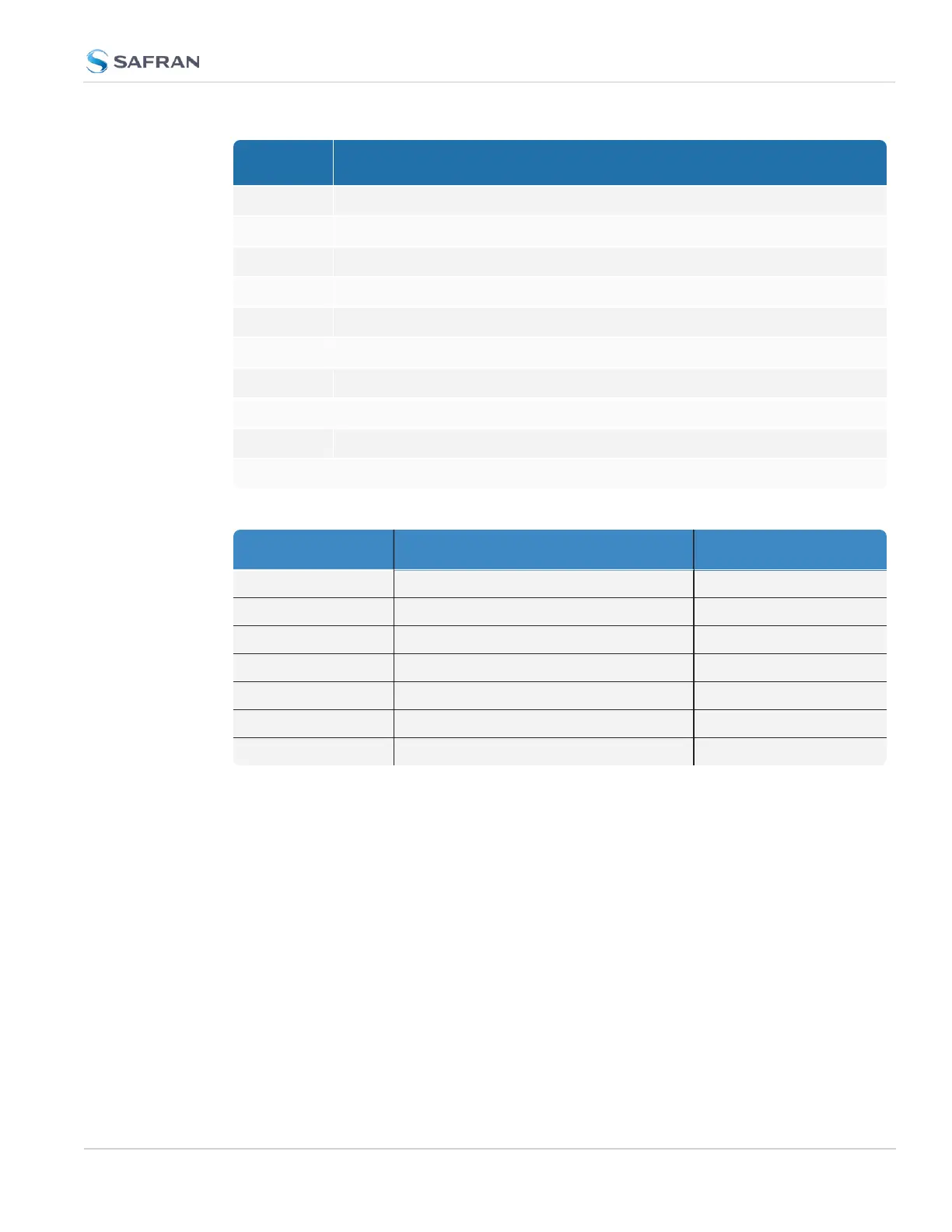
Pin Signal
6 DCLS OUT
7 GND
8 GND
9 GND
10 GND
11 IRIG AM OUT
12 GND
13 (First signal) RS485 B, inverting
14 (Second signal) RS485 B, inverting
15 RS232 RX IN
Table 1-10: Multi I/O signal defaults
Pins Channel Default Signal
6 & 7 DCLS OUT IRIG OUT
1 & 2 DCLS IN IRIGIN
15 & 10 RS232 IN ATC IN
5 & 10 RS232 OUT ATC OUT
3, 8, 13 RS485 (1) HAVEQUICK OUT
4, 9, 14 RS485 (2) HAVEQUICKIN
11 & 12 IRIG AM OUT IRIGOUT(AM ONLY)
1.6.5 DCLS Output
The rear panel DCLS OUT BNC female connector defaults to a 1PPS Output (see
below), but can be configured to produce different output signals: IRIG Output,
HaveQuick Output, and GPIOOutput. For more information, see "Configurable
Connectors" on page157.
1.6.5.1 1PPS Output
Signal: One pulse-per-second square wave (ext. reference connected to GNSS
receiver)
Signal level: TTL compatible, 4.3 V minimum, base-to-peak into 50 Ω
1.6 Specifications
CHAPTER 1 • SecureSync 2400 User Manual Rev. 5.2
29