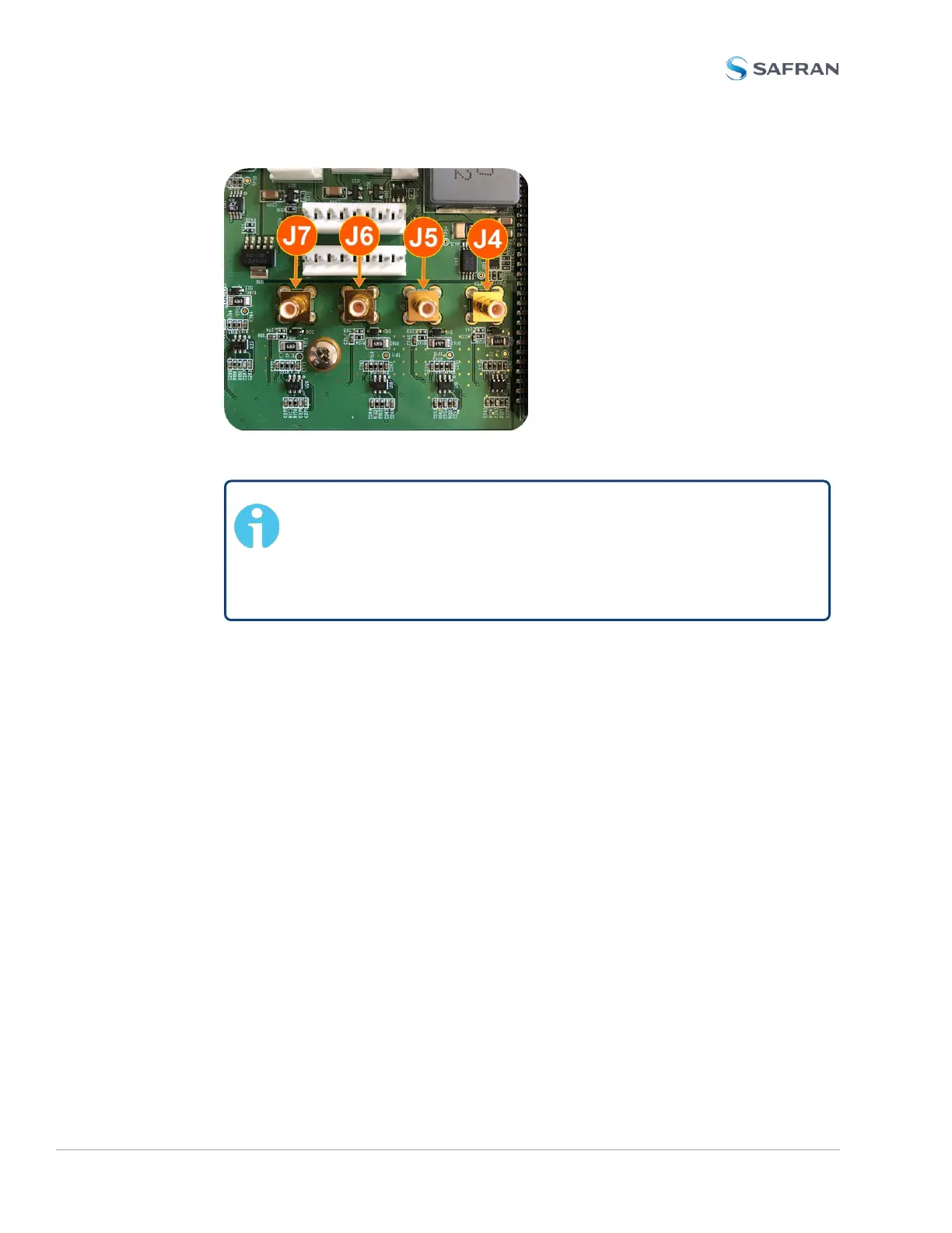
Figure 5-10: J Connectors
Note: For 10MHz option cards with 3 coax cables: From the
rear of the option card, outputs are labeled J1, J2, J3. Start by
connecting the cable attached to J1 on the card to the first avail-
able open connector on the SecureSync mainboard, then con-
nect the cable attached to J2, then J3, etc.
b. Using the supplied cable ties, secure the coax cable from the option card to
the white nylon cable tie holders fastened to the mainboard.
5.2.2.12 [9]: Alarm Relay Card, Cable Installation
Additional steps for the installation of the Alarm Relay Output card (PN1204-
0F).
a. Connect the supplied cable, part number 8195-0000-5000, to the main-
board connector J19, pins 3 - 8.
Note: Pins 1 and 2 of connector J19 are not used:
382 SecureSync 2400 User Manual
APPENDIX