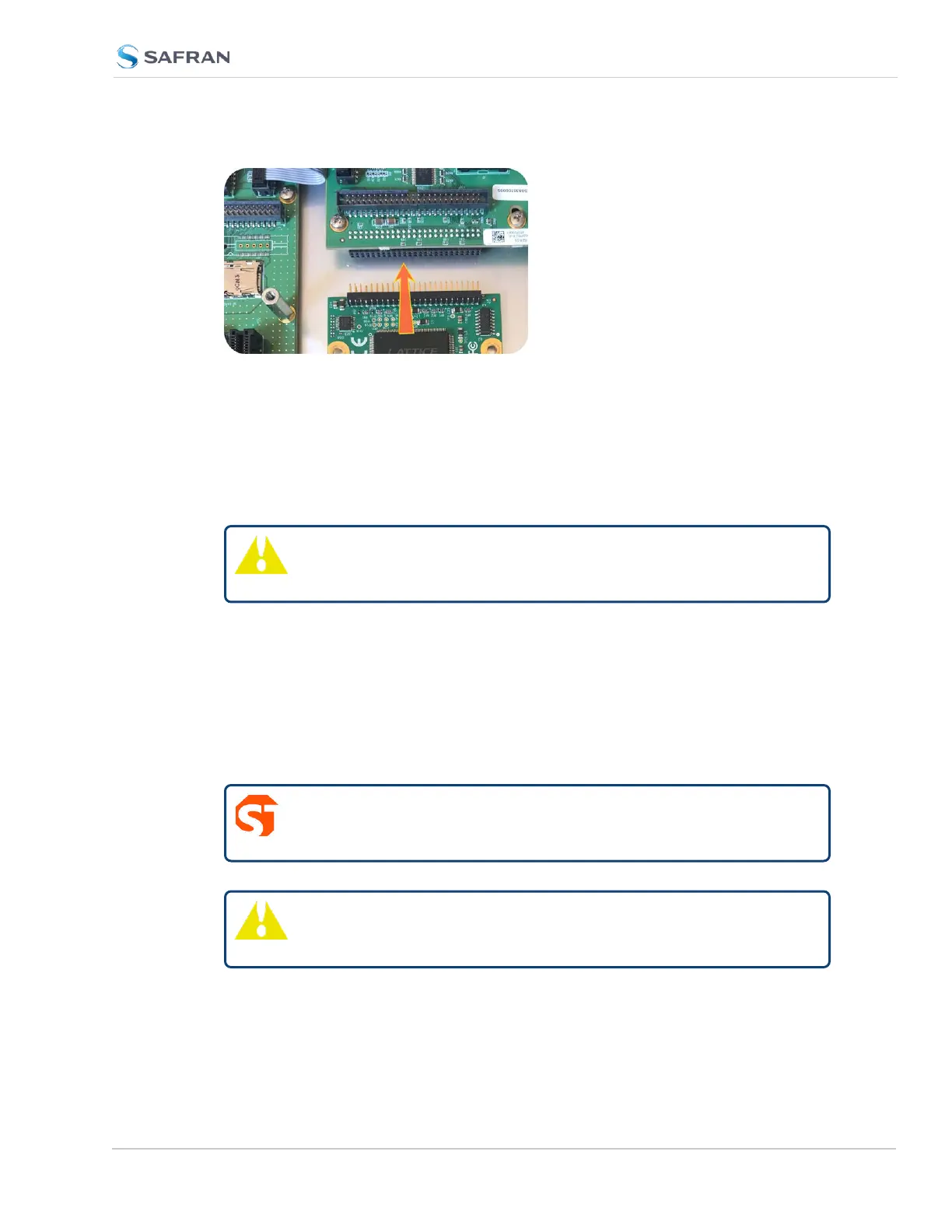
Figure 5-5: Connector installation
d. Using the supplied M3 screws, screw the board, and the option card plate
into the chassis, applying a torque of 0.9Nm/8in-lbs.
If you are reinstalling an option card above this one, you should instead fol-
low the instructions for "[7]: Top Slot Installation, Bottom Slot Occupied"
on page379 (you will be using standoffs in this situation).
Caution: Align and secure screw holes to chassis to avoid
equipment damage.
5.2.2.9 [6]: Top Slot Installation, Bottom Slot Empty
Instructions for installing an option card into an upper slot (4, or 6) of the
SecureSync unit, with no card populating the bottom slot:
a. Safely power down your SecureSync unit and remove the top cover of the
main chassis (housing). Save the screws.
DANGER! SecureSync does not have an ON/OFF switch. It is
necessary to unplug the machine to remove power!
Caution: NEVER install an option card from the rear of the unit,
ALWAYS from the top, after removing the chassis cover.
SecureSync 2400 User Manual 377
APPENDIX