The following configuration instructions apply to optional inputs on the basic unit
model. For specifics on inputs made available through option cards, see the sec-
tion "Option Cards" on page361.
2.19.2 Configure a 1PPS Input
A 1PPS Input can be set up through the Multi-I/O connector (see "Configurable
Connectors" on page157).
To configure the settings of the PPS Input (also referred to as ‘Reference’), go to
its Edit window..
The Web UI list entries for these cards are:
1PPS In/Out
1PPS In/Out, Fiber
The connector number for the input is: J1
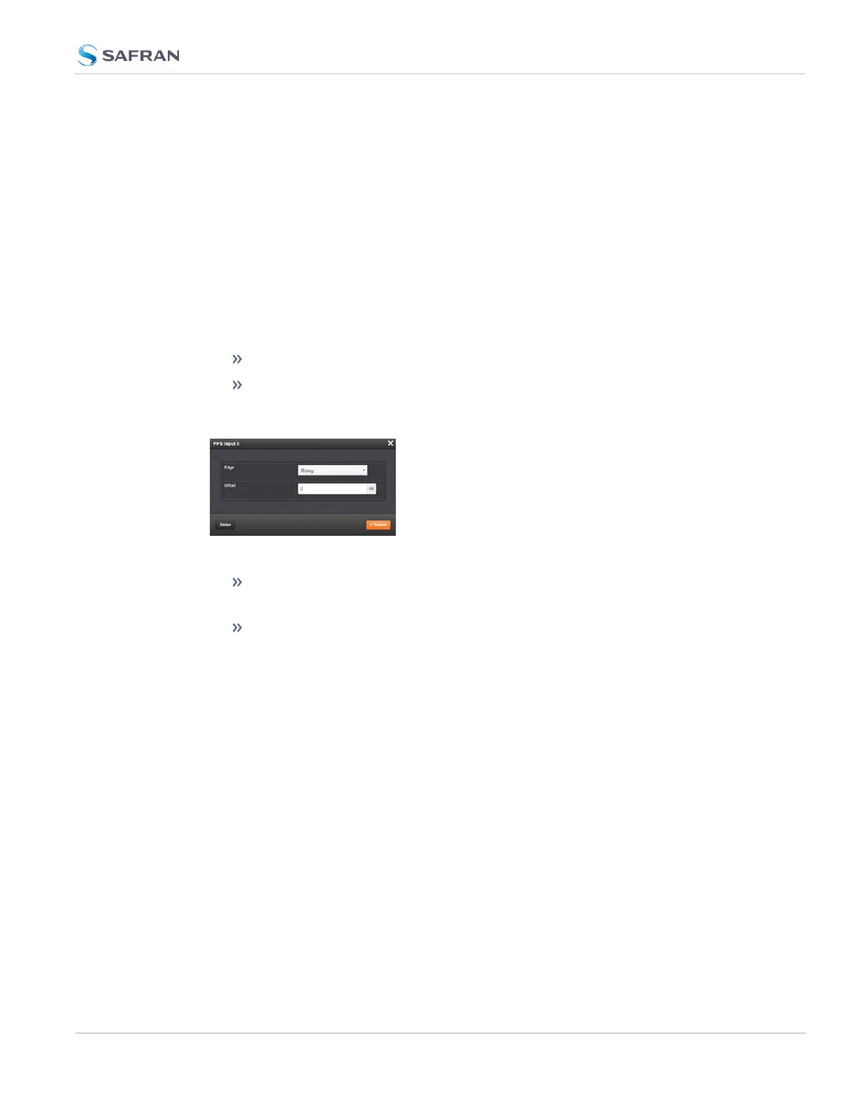
The Edit window allows the configuration of the following settings:
Edge: The operator can select either the rising or the falling edge as the
input time reference (defines the on-time point of the signal).
Offset: It is possible to add an offset to the input signal (to account for
cable delays), with a resolution of 5ns and a positive or negative value of
500ms maximum.
2.19.3 Configure an ASCIIInput
An ASCII Input is available by default configuration through the Multi-I/O con-
nector (see "Configurable Connectors" on page157).
To configure the ASCII Input (also referred to as ‘Reference’), go to its Edit win-
dow.
2.19 Configuring Input References
CHAPTER 2 • SecureSync 2400 User Manual Rev. 5.2
163


 To Next Page