Figure 5-4: Standoffs location
e. Using the supplied M3 screws, screw the board, and the option card plate
into the chassis, applying a torque of 0.9Nm/8in-lbs.
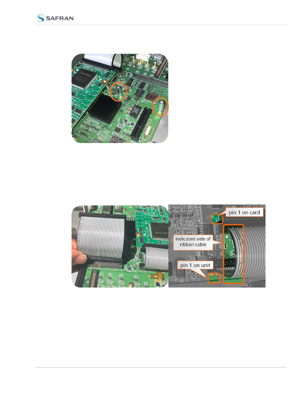
f. Take the supplied 50-pin ribbon cable and carefully press it into the con-
nector on the mainboard (lining up the indicated end of the cable with PIN 1
on the mainboard), then into the connector on the option card (see
Figurebelow).
SecureSync 2400 User Manual 375
APPENDIX