d. Remove screws securing the card already populating the bottom slot. Save
the screws.
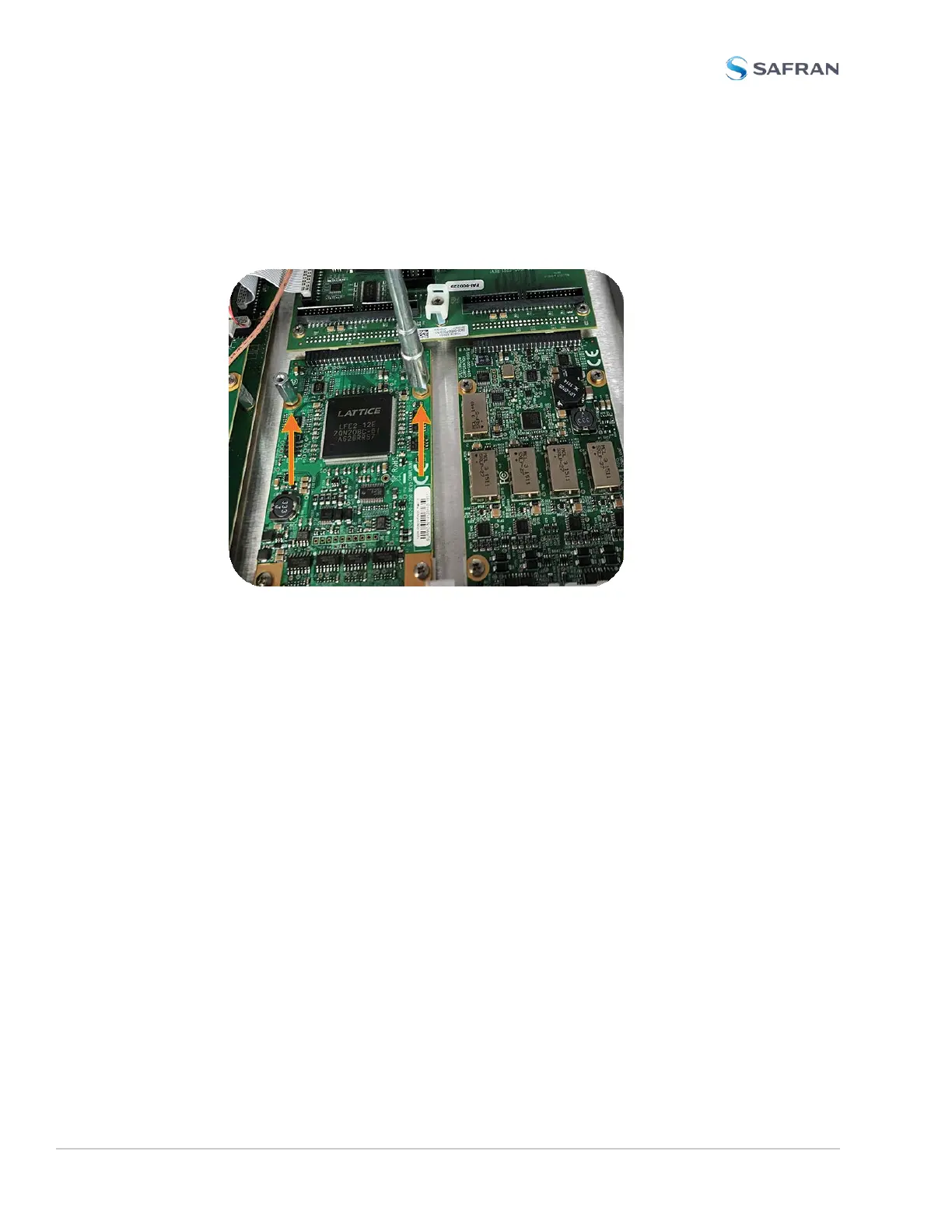
e. Screw the 18-mm standoffs into the option card populating the bottom slot
(see Figurebelow) , applying a torque of 0.9Nm/8in-lbs.
Figure 5-8: Bottom card with standoffs installed
f. Insert option card into the slot above the existing card, lining up the screw
holes with the standoffs.
g. Using the supplied M3 screws, screw the board into the standoffs, and the
option plate into the chassis, applying a torque of 0.9Nm/8in-lbs.
h. Take the supplied 50-pin ribbon cable and carefully press it into the con-
nector on the extension board (lining up the ribbon cable with PIN 1 on the
board with PIN 1 on the card), then into the connector on the option card
(see Figurebelow).
380 SecureSync 2400 User Manual
APPENDIX