Figure 5-50: Model 1204-02 option card rear plate
Pin Assignments: OUTPUT connector J1
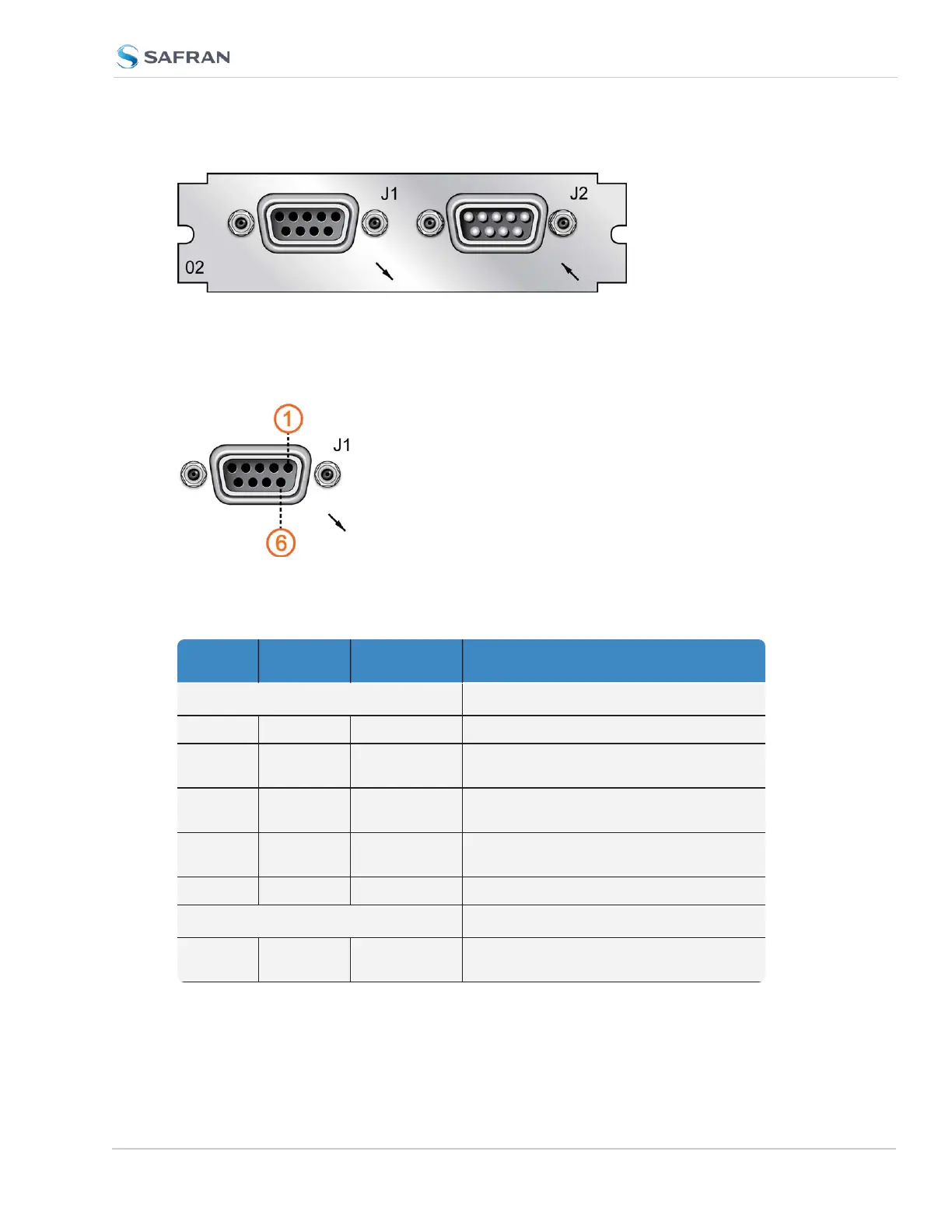
Figure 5-51: OUTPUT connector J1
Table 5-22: Pin-out, OUTPUT connector "J1"
Pin Num-
ber
Signal Function Notes
Top row of 5 pins
1 PPS_OUT 1PPS output TTL level on 50Ω
2 SERIAL_
OUT_TX
RS-232 Trans-
mit data
Data output (ToD messages)
3 SERIAL_
IN_RX
RS-232
Receive data
Data input into unit; use this to transmit
commands to the unit)
4 NC No con-
nection
5 GND Ground
Bottom row of 4 pins
6 NC No con-
nection
SecureSync 2400 User Manual 485
APPENDIX