Fig. 3-3 1022 – Explanation of the symbols (part 3)
- 1022 -
Function diagram
87654321
fp_1022_97_61.vsd
Explanations on the function diagrams
G120 CU240B/E-2
09.12.2015 V4.7.6
Explanation of the symbols (part 3)
T0xy
pxxxx
yx
H(s) =
s
2
2
• s + 1
+
+
s
2
2
2 •
2
2
f
2nd Order Filter
|y|
fs
f_B
t
y
pxxxx
H(s) =
+
s
2
2
• s + 1
2 •
2
1
yx
f
|y|
fn
D
0Txy
pxxxx
T1 T2
T0
pxxxx
0T
pxxxx
xy
xy
xy
T1 T2
xy
pxxxx pyyyy
pxxxx pyyyy
x
T
y
x
y
x
T
y
T1 T1 T2 T2
y
x
1
I
x
2
f_B
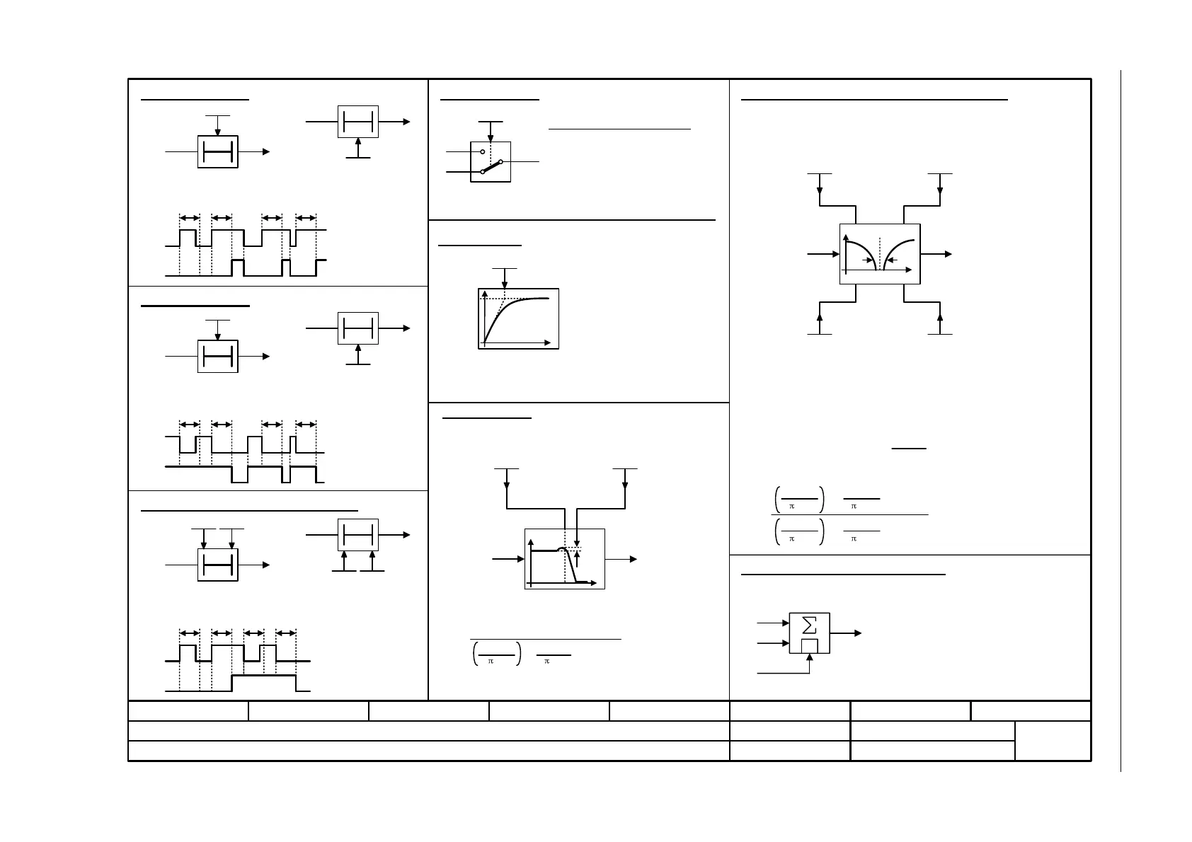
Switch-on delay
The digital signal x must have the value "1" without any interruption
during the time T before output y changes to "1".
Switch-off delay
The digital signal x must have the value "0" without interruption
during the time T before output y changes to "0".
Delay (switch-on and switch-off)
PT1 element
Delay element, first order.
pxxxx = time constant
PT2 low pass
Damping, denominator
D_d
pyyyy
Natural frequency, denominator
fn_d
pxxxx
Damping, denominator
D_d
pyyyy
Natural frequency, denominator
fn_d
pxxxx
Transfer function
2nd-order filter (bandstop/general filter)
Natural frequency, numerator
fn_n
pzzzz
Damping, numerator
D_n
pwwww
Used as bandstop filter
- center frequency fs: fn_n = fs
fn_d = fs
- bandwidth f_B: D_n = 0
D_d =
Transfer function when used as general filter
Analog adder can be activated
The following applies to I = 1 signal: y = x1 + x2
The following applies to I = 0 signal: y = x1
The digital signal x must have the value "1" without interruption
during time T1 or must have the value "0" during time T2 before
output y changes its signal state.
2 •
• s + 1
2 • fs
TTT
TTT
1
0
pxxxx
Switch symbol
Simple changeover switch
The switch position is shown according
to the factory setting of pxxxx
(in this case switch position 1).
fn_n
D_n
fn_d
D_d
fn_d
fn_d
fn_n
fn_d
D_d

 Loading...


