3 Function diagrams
3.15 Vector control, Dynamic Drive Control (p0096 = 2)
SINAMICS G120 Control Units CU240B-2/CU240E-2
710 List Manual (LH11), 01/2016, A5E33839529
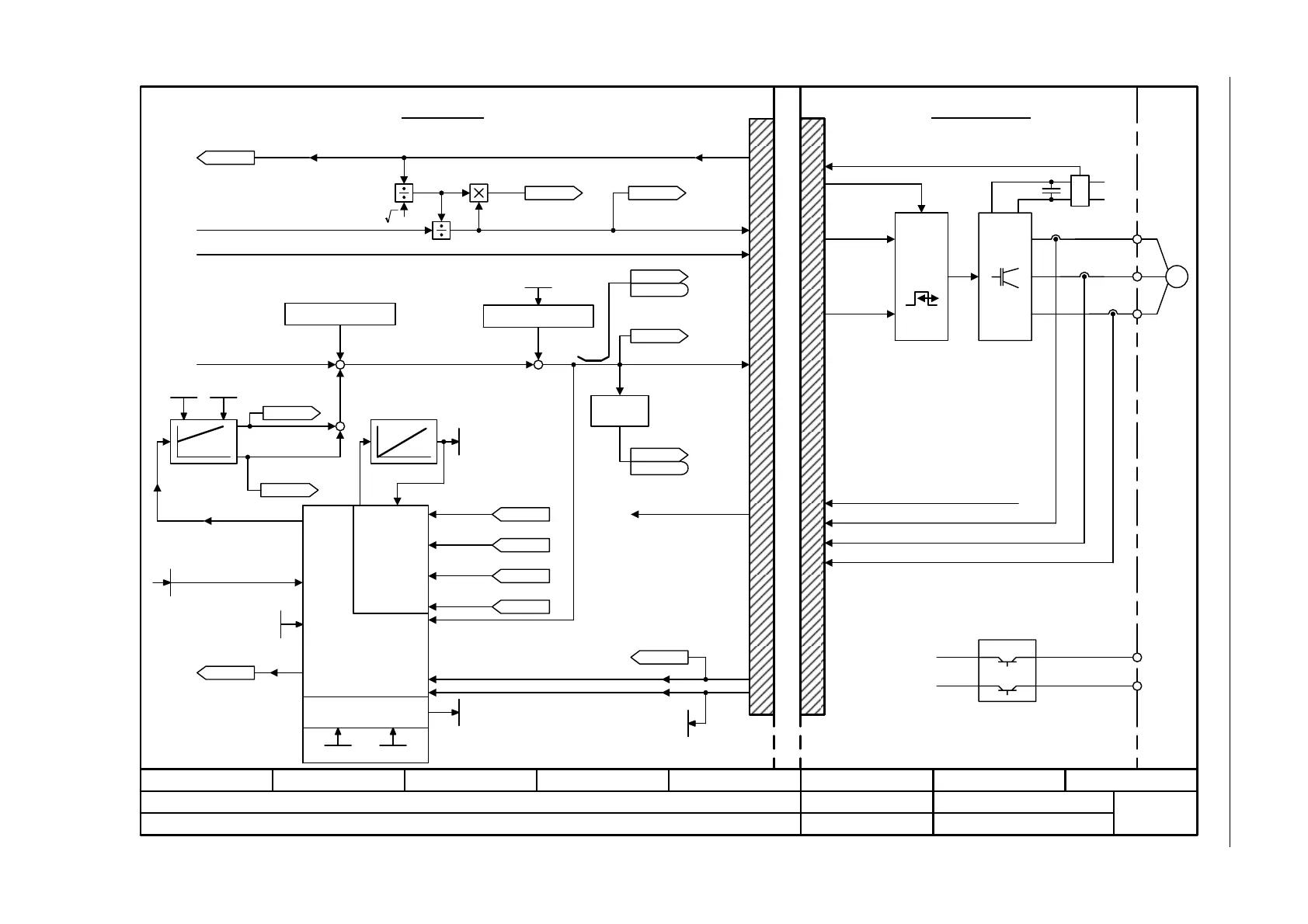
Fig. 3-135 6842 – Interface to the Power Module (PMSM, p0300 = 2xx, p0096 = 2)
- 6842 -
Function diagram
87654321
fp_6842_97_56.vsd
Vector control, Dynamic Drive Control
G120 CU240B/E-2
09.12.2015 V4.7.6
Interface to the Power Module (PMSM, p0300 = 2xx, p0096 = 2)
PWM
M
~
U
V
W
P24
M
[6828.1]
[6799.1]
[6834.8]
[6839.1]
[6799.1]
[8022.1]
[6834.1]
p1764 p1767
[2526.2]
Pre-control speed
Brake control
I_max PM
Pulse enable HW
DC link voltage (Vdc)
Power ModuleControl Unit
U_set
U_angle
Motor model
r1762, r1778
Model control
kT estimator
p0328
r0334
p0357
p1780.3
r0070
Vdc act val [V]
ZSW cl-loop ctrl
r0056
r0056
r0066
f_outp [Hz]
ZSW cl-loop ctrl
r0056
r0056
MotMod kT corr [Nm/A]
r1797 [D]
r0094
Transformat_angle [°]
R_stator act [Ohm]
r0395 [D]
Vibration damping
Sign
+ or -
Current model
Gain res_damp
p1740
p1755 p1756
Outp_ph_seq rev
p1820
+
+
+
+
+
.11
.7
– BRN
+ BRN
I_max PM
[6836.6]
r0077
Iq_set [Arms]
r0076
Id_act [Arms]
r1732
Direct U set [Vrms]
[0]
r1733
Quad U set [Vrms]
[6836.4]
r0069
I_phase act val [A]
[0..6]
MotMod status
r1751
U_phase act val [V]
r0089[0..2]
[6822.8]
r1770
MotMod n_adapt
Kp [rpm]
r1771
MotMod n_adapt
Tn [rpm]
[6834.8]
[2526.2]
[6799.1]
[8022.1]
[6799.5]
r0072
U_output [Vrms]
r0074
Mod_depth [%]
2
Power Module Interface
+
-
PMSM: Permanent-magnet synchronous motor

 Loading...


