3 Function diagrams
3.9 Safety Integrated Basic Functions
SINAMICS G120 Control Units CU240B-2/CU240E-2
634 List Manual (LH11), 01/2016, A5E33839529
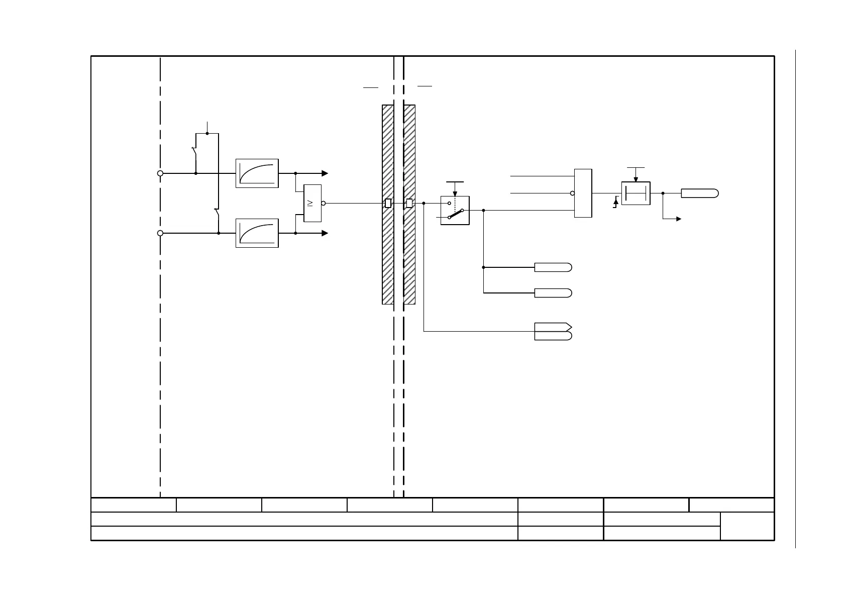
Fig. 3-65 2812 – STO (Safe Torque Off) (Part 2) - PM240-2 FS D-F
- 2812 -
Function diagram
87654321
fp_2812_97_56.vsd
Safety Integrated Basic Functions
CU240E-2/E-2_DP
09.12.2015 V4.7.6
STO (Safe Torque Off) (part 2) - PM240-2 FS D-F
STO_B
1
&
STO_A
DIP_A
DIP_B
+24 V
Power Module Interface
0
1
0
r9772.25
r9872.25
DIAG_U
Shutdown lower
IGBT bridge
halve
[2810.7]
[2810.7]
PM
CU
T0
FCP_dyn STO PM-T t
p9661
r9773.30
A01678
[2804.1], [2810.5]
1 = STO cause, selection via terminal on Power Module
1 = STO cause, selection via onboard PM terminal
1 = PM terminals shutdown
paths must be tested
[2810.5]
[2810.6]
[2804.3]
[2804.6]
4 ms
p9601.7/
p9801.7
4 ms
<1>
<1> Switch-on delay starts when the "request pulse
suppression P1" is withdrawn.
Missing enable sig
r0046
r0046
.8
[2634]
SI: Test stop for STO via
terminals required at the PM
Shutdown upper
IGBT bridge
halve
1 = No request pulse
suppression P1
Power Module
Enable STO

 Loading...


