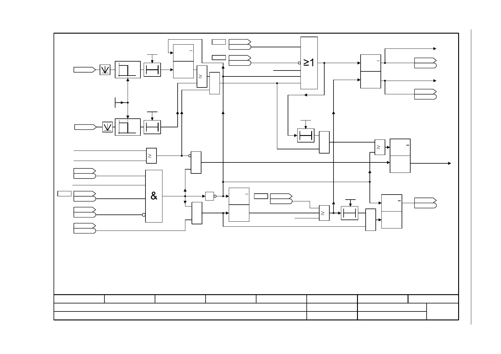
Fig. 3-60 2701 – Basic brake control
- 2701 -
Function diagram
87654321
fp_2701_97_57.vsd
Brake Control
G120 CU240B/E-2
09.12.2015 V4.7.6
Basic brake control
1
T0
T0
p1215 = 2
1
0
1
0
T0
1
1
1
<3>
T0
[2503.3]
[2503.3]
&
<1>
<1>
[2501.3]
p0855
<4>
[2503.3]
<5>
<6>
[2501.3]
p0858
[2501.3]
p0852
[2503.7]
[2503.7]
Q
Q
RESET
(Q=0)
SET
(Q=1)
Q
Q
RESET
(Q=0)
SET
(Q=1)
Q
Q
RESET
(Q=0)
SET
(Q=1)
Q
Q
RESET
(Q=0)
SET
(Q=1)
Q
Q
RESET
(Q=0)
SET
(Q=1)
<2>
p1215 = 0
p0856
&
&
&
1
&
<7>
n_standst n_thresh
0.00 ... 210000.00 [rpm]
p1226 [D] (20.00)
ZSW seq_ctrl
r0899
r0899
r0063
n_act [rpm]
n_standst t_monit
0.000 ... 300.000 [s]
p1227 (300.000)
OFF 1 present
OFF 3 present
1 = No coast down active
Pulse enable
1 = Operation enabled
1 = Switching on
inhibited active
1 = Magnetizing completed
STW seq_ctrl
r0898
r0898
ZSW seq_ctrl
r0899
r0899
Missing enable sig
r0046
r0046
.21
unsmoothed
Pulse suppr t_del
0.000 ... 299.000 [s]
p1228 (0.010)
Brake t_close
0 ... 10000 [ms]
p1217 (100)
1 = Enable speed
controller
STW seq_ctrl
r0898
r0898
1 = Unconditionally close
the holding brake
STW seq_ctrl
r0898
r0898
.14
Brake t_open
0 ... 10000 [ms]
p1216 (100)
1 = Unconditionally
open the holding brake
STW seq_ctrl
r0898
r0898
.7
1 = Command, close holding brake
PU enable internal missing
Pulse enable HW
1 = Holding brake open
ZSW seq_ctrl
r0899
r0899
ZSW seq_ctrl
r0899
r0899
1 = Open the holding brake
Close "normal" brake
Close brake
Open brake
Priority assignment (high -> low): p1215, p0858, p0855, p0856, sequence control.
If p1215 = 0, 2 -> t = 0 ms.
Only if "Safety Integrated" is active.
If an external motor holding brake is used, p1215 should be set to 3 and r0899.12 should be interconnected as control signal.
r0046.21 = 0, as long as r0046.0 = 1 (OFF1 enable missing or switching on inhibited).
r0046.21 = 1, if p0858 = 1 or p0856 = 0.
The signal generation is shown simplified.
The internal signal includes signals that lead to OFF1 or OFF3 (e. g. BICO or fault response).
If the brake is permanently applied or released (p0855, p0858 or p1215) the drive does not wait while the brake is released or applied.
ZSW cl-loop ctrl
r0056
r0056
[2526.6]
[6030.2]
Start frequency with U/f control: p1351, p1352 [6310.6]; Start torque with vector control: p1475 [6040.3].
r0060
n_set before filt.
[rpm]
.12
.13
.12
.4
.6
.3
.4
[6730.6], [6731.6]
[0]
<8><2>
<1>
<2>
<3>
<4>
<5>
<6>
<7>
<8>

 Loading...


