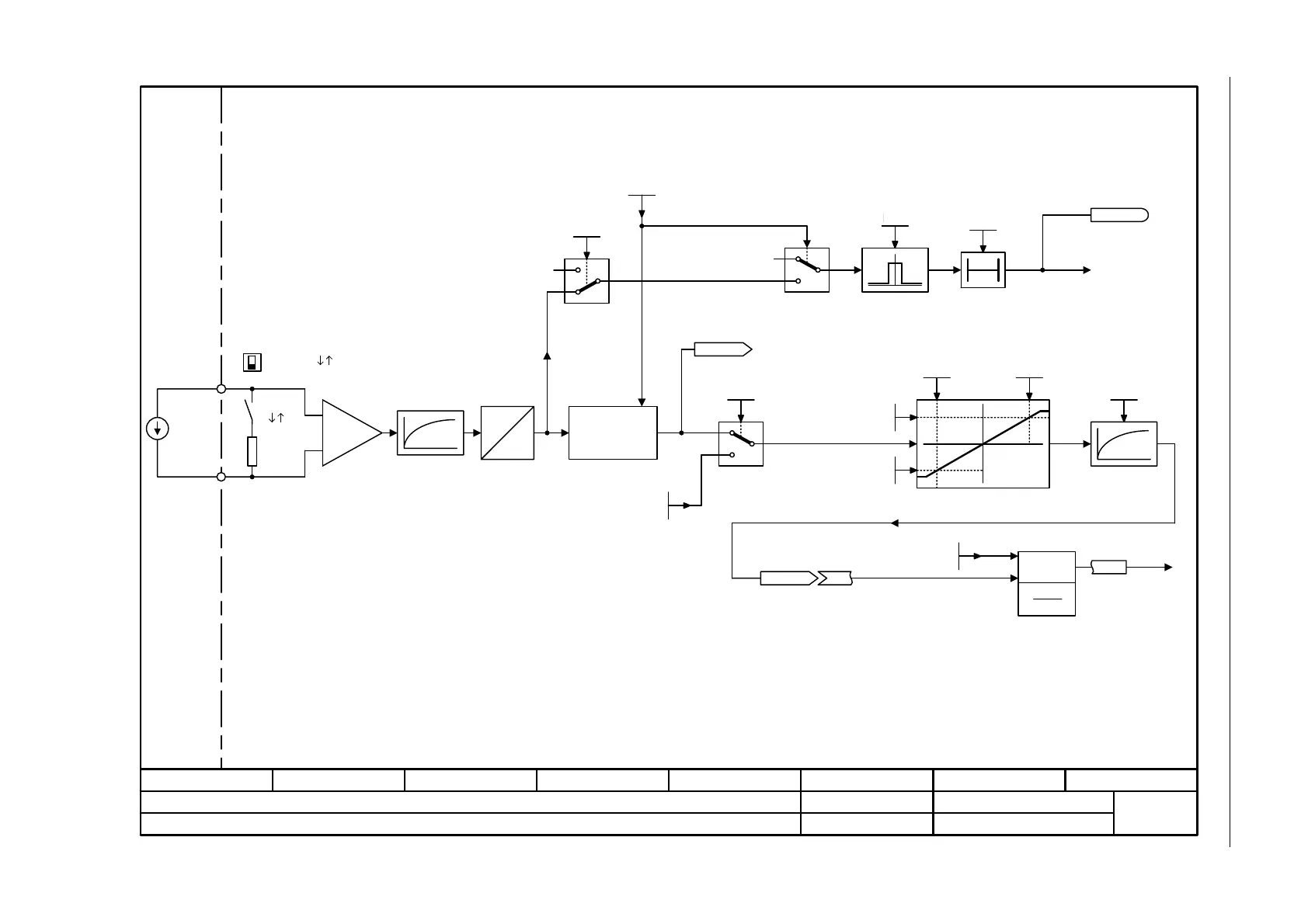
Fig. 3-11 2250 – CU240B-2: Analog input 0 (AI 0)
- 2250 -
Function diagram
87654321
fp_2250_97_02.vsd
Input/Output Terminals
G120 CU240B-2
09.12.2015 V4.7.6
CU240B-2: Analog input 0 (AI 0)
3
3
T0
[%]
xy
A
D
x
1
y
2
x
2
y
1
y
x
[%]
Bezugsgrößen
p2000...r2004
y
x
2
x
1
I
1
0
1
0
Voltage
Current
Hardware smoothing
100 µs
Scaling
Differential Input!
For an input signal referred to ground, terminal 4 must be connected to reference potential M.
Notice:
The voltage between inputs and between input and the ground point must not exceed 35 V.
When the load resistor is switched in (DIP switch in position ĹI), the voltage between the input terminals
must not exceed 10 V or the impressed current 80 mA. If this is not observed the input will be damaged.
For p0756 = 2, 3 the units are mA.
For p0756 = 0, 1, 4 the units are V.
Possible settings p0756[0]:
= 0: 0 V ... +10 V
= 1: +2 V ... +10 V with monitoring
= 2: 0 mA ... +20 mA
= 3: 4 mA ... +20 mA with monitoring
= 4: -10 V ... +10 V (Default for AI 0)
F03505
"Wire
breakage"
r0752
CU AI U/I_inp act
Wire breakage sensing only activated when p0756 = 1, 3.Kl. = Terminal
Sampling time of the AI: 4 ms
r0755
CU AI value in % [%]
Type switching
Analog input
U
CU AI status word
r0751
CU WireBrkThresh
0.00 ... 20.00
p0761[0..1] (2.00)
CU wire brk t_del
0 ... 1000 [ms]
p0762[0..1] (100)
CU AI sim_mode
0 ... 1
p0797[0..1] (0)
CU AI sim setp
-50.000 ... 2000.000
p0798[0..1] (0.000)
CU AI char y1
-1000.00 ... 1000.00 [%]
p0758[0..1] (0.00)
CU AI char y2
-1000.00 ... 1000.00 [%]
p0760[0..1] (100.00)
CU AI char x1
-50.000 ... 160.000
p0757[0..1] (0.000)
CU AI char x2
-50.000 ... 160.000
p0759[0..1] (10.000)
CU AI T_smooth
0.0 ... 1000.0 [ms]
p0753[0..1] (0.0)
CU AI type
0... 8
p0756[0..1] (4)
CU AI sim_mode
0 ... 1
p0797[0..1] (0)
AI 0
U I
AI 0
U I
<1>
Kl. 3
Kl. 4
0 … 20 mA
-10 … +10 V
<1>
<2>
20 mA
[0] (0)
20 mA
[0] (4)
<2> <3>
[0] (0)
<2>
[0] (2.00)
[0] (100)
[0] (0.000)
<2>
[0] (0.000)
[0] (100.00)
[0] (0.000) [0] (10.000)
[0] (0.0)
[0]
<2> <2>
<4>
<3>
<4>
–
+
x
x
1
• x
2
100 %

 Loading...


