SINAMICS G120 Control Units CU240B-2/CU240E-2
List Manual (LH11), 01/2016, A5E33839529
577
3 Function diagrams
3.3 Input/output terminals
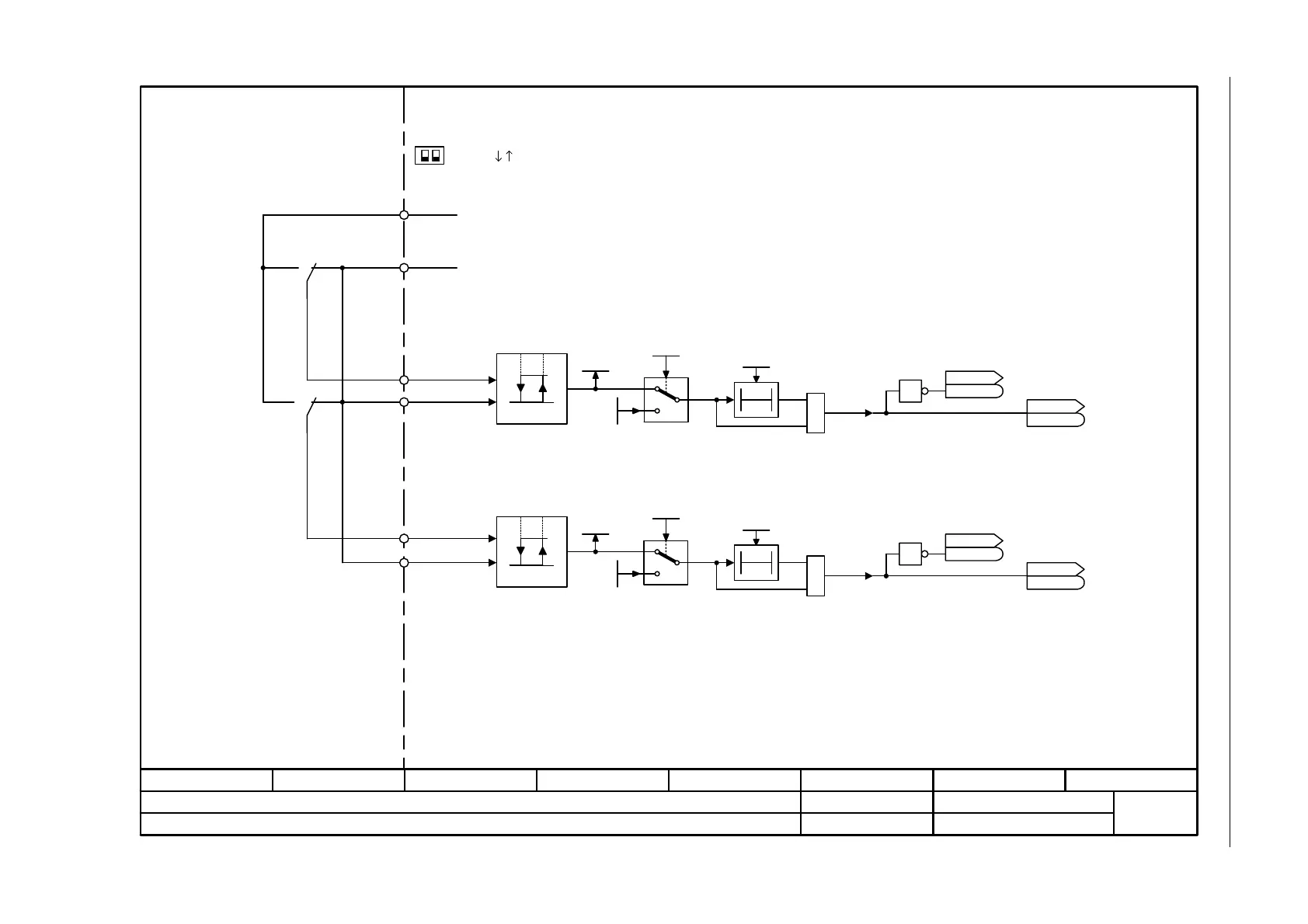
Fig. 3-14 2256 – CU240E-2: Analog inputs as digital inputs (DI 11 ... DI 12)
- 2256 -
Function diagram
87654321
fp_2256_97_52.vsd
Input/Output Terminals
G120 CU240E-2
09.12.2015 V4.7.6
CU240E-2: Analog inputs as Digital inputs (DI 11 … DI 12)
1
0
1
r0721.11
p0796.11
CU DI status inv
r0723
r0723
CU DI status
r0722
r0722
CU DI simulation
p0795
1 = Simulation on
T0
CU DI t_debounce
p0724
0
1
1.6 V 4.0 V
Sampling time of the DI: 4 ms
&
1
0
1
r0721.12
p0796.12
CU DI status inv
r0723
r0723
CU DI status
r0722
r0722
T0
CU DI t_debounce
p0724
0
1
1.6 V 4.0 V
&
.11
.11
.12
.12
.12
.11
<1>
Kl. 2
Kl. 3
Kl. 4
Kl. 10
Kl. 11
GND
+10 V OUT
AI 0+ (DI 11)
AI 0-
AI 1-
AI 1+ (DI 12)
1 = Simulation on
CU DI simulation
p0795
(Kl. 9) (+24 V OUT)
Kl. = Terminal
Voltage
Current
U I
AI 0/1
II
UU
Notice:
The operating mode selector switch of the
analog input has to be set to "Voltage" (U).
The 10 V or 24 V voltage source will destroy
the analog input if the operating mode
selector switch is set to "Current input" (I).
<1>
Kl. 1

 Loading...


