Execution in manual mode
3.6 Simple face milling of workpiece
Milling
132 Operating Manual, 03/2010, 6FC5398-7CP20-1BA0
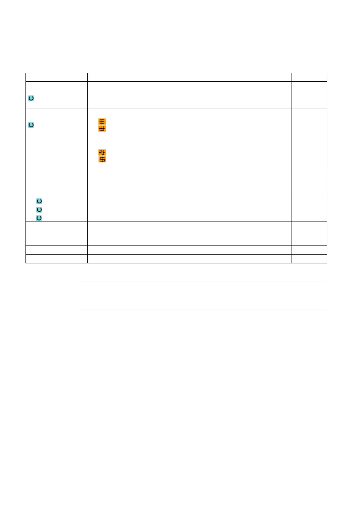
Parameters Description Unit
Machining
The following machining operations can be selected:
∇ (roughing)
∇∇∇ (finishing)
Direction
Same direction of machining
Alternating direction of machining
X0,
Y0
Z0
Corner point 1 of surface in X direction (abs. or inc.)
Corner point 1 of surface in Y direction (abs. or inc.)
Height of blank (abs. or inc.)
mm
mm
mm
X1
Y1
Z1
Corner point 2 of surface in X direction (abs. or inc.)
Corner point 2 of surface in Y direction (abs. or inc.)
Height of finished part (abs. or inc.)
mm
mm
mm
DXY Max. infeed in the XY plane (dependent on milling cutter diameter)
Alternatively, you can specify the plane infeed as a %, as a ratio → plane infeed
(mm) to milling cutter diameter (mm).
mm
%
DZ Max. infeed in Z direction - (only for roughing) mm
UZ Finishing allowance, depth mm
Note
The same finishing allowance must be entered for both roughing and finishing. The finishing
allowance is used to position the tool for retraction.
See also
Tool, offset value, feed and spindle speed (T, D, F, S, V) (Page 229)

 Loading...


