Ladder Viewer and Ladder add-on (828D only)
19.2 Structure of the user interface
Milling
560 Operating Manual, 03/2010, 6FC5398-7CP20-1BA0
19.2 Structure of the user interface
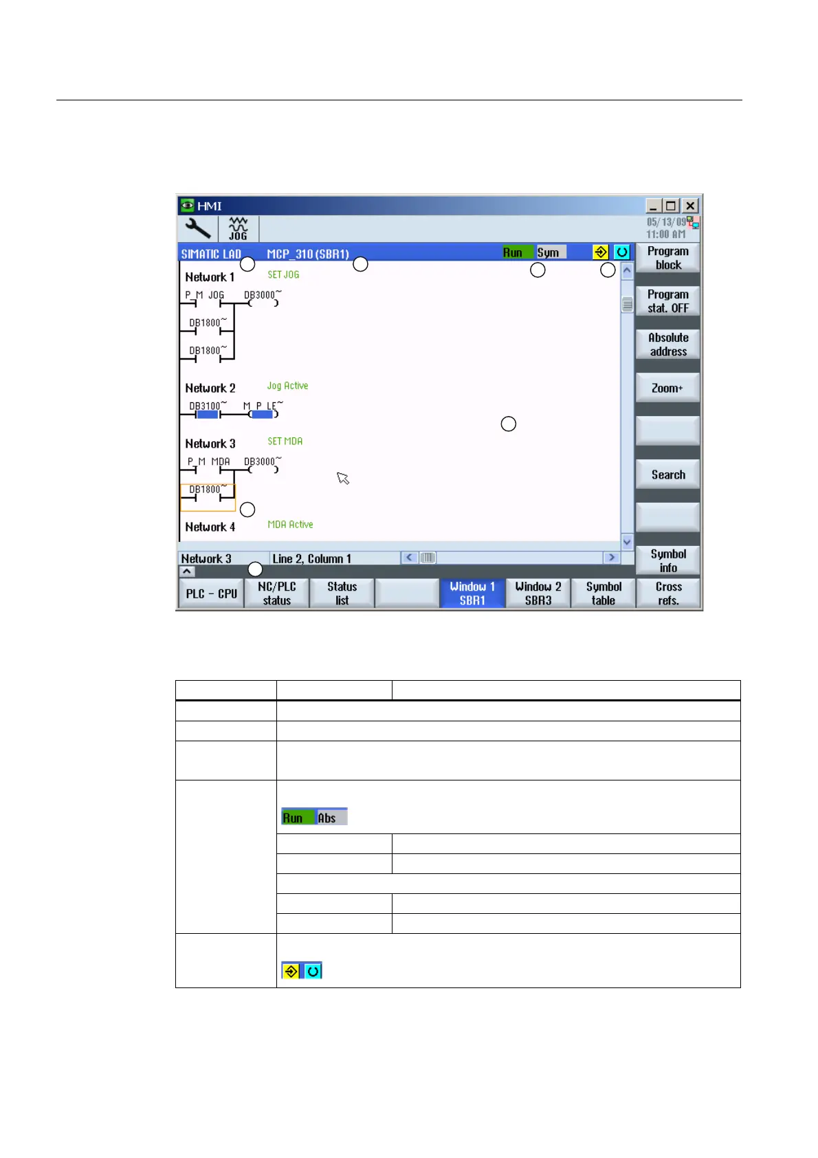
Figure 19-1 Screen structure
Table 19- 1 Key to screen layout
Screen element Display Meaning
1 Application area
2 Supported PLC program language
3 Name of the active program block
Representation: Symbolic name (absolute name)
Program status
Run Program is running
Stop Program is stopped
Status of the application area
Sym Symbolic representation
4
Abs Absolute representation
5 Display of the active keys (<INPUT>, <SELECT>)

 Loading...


