Setting up the machine
2.6 Measuring the workpiece zero
Milling
Operating Manual, 03/2010, 6FC5398-7CP20-1BA0
83
Automatic measurement
1. Prepare the measurement (see steps 1 to 6 above).
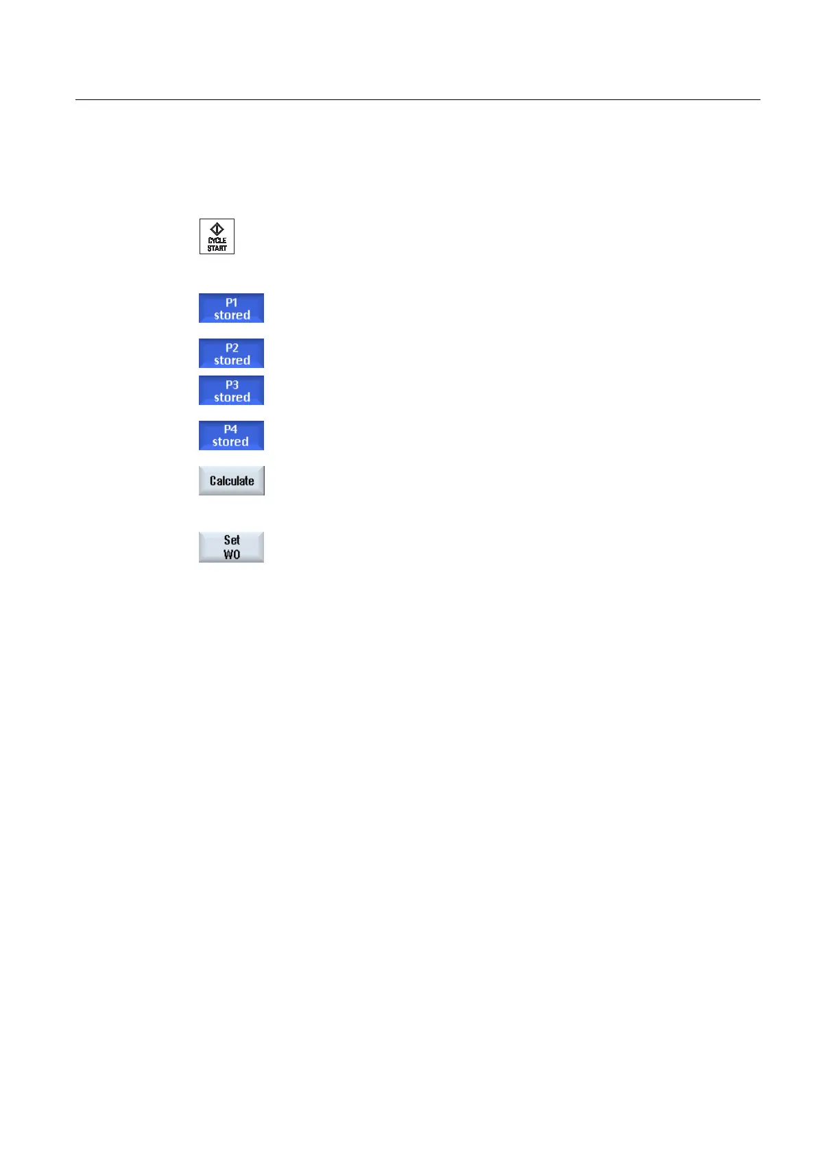
2. Approach measuring point P1 with the workpiece probe and press the
<CYCLE START> key.
This starts the automatic measuring process. The position of
measuring point 1 is measured and stored.
The "P1 stored" softkey becomes active.
3. Repeat the operation to measure and store points P2 and P3.
If you are measuring a corner not equal to 90°, repeat the procedure
to measure and store point P4.
4. Press the "Calculate" softkey.
The corner point and angle α are calculated and displayed.
- OR -
Press the "Set WO" softkey.
The corner point now corresponds to the setpoint position. The
calculated offset is stored in the offset target that you have selected.
2.6.8 Measuring a pocket and hole
You can measure rectangular pockets and one or more holes and then align the workpiece.
Measuring a rectangular pocket
The rectangular pocket must be aligned at right-angles to the coordinate system. By
automatically measuring 4 points inside the pocket, its length, width and center point can be
determined.
Measuring 1 hole
The workpiece with the hole to be measured is clamped to the work table in any position. In
the hole, 4 points are automatically measured, and from this measurement, the diameter and
center point of the hole are determined.
Measuring 2 holes
The workpiece with the two holes to be measured is clamped to the work table in any
position. 4 points are automatically measured in both holes and the hole centers are
calculated from them. Angle α is calculated from the connecting line between both center
points and the reference axis, and the new zero point that corresponds to the center point of
the 1st hole is determined.