Setting up the machine
2.6 Measuring the workpiece zero
Milling
80 Operating Manual, 03/2010, 6FC5398-7CP20-1BA0
Automatic measurement
1. Prepare the measurement (see steps 1 to 5 above).
2. Traverse the workpiece probe close to the workpiece edge on which
you wish to measure and press the <CYCLE START> key.
This starts the automatic measuring process. The position of
measuring point 1 is measured and stored.
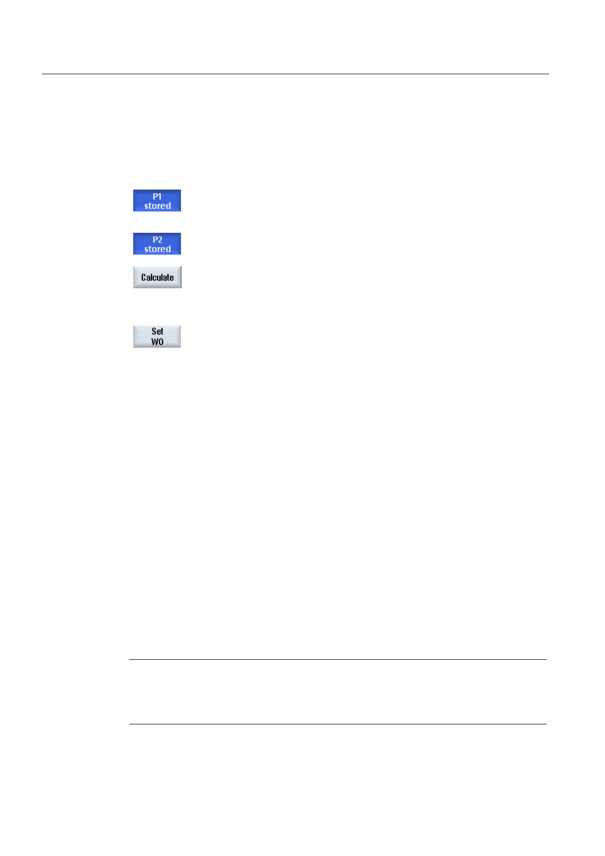
The "P1 stored" softkey becomes active.
3. Repeat the operation to measure and store P2.
4. Press the "Calculate" softkey.
The angle between the workpiece edge and reference axis is
calculated and displayed.
- OR -
Press the "Set WO" softkey.
With "Set WO", the workpiece edge now corresponds to the setpoint
angle.
The calculated rotation is stored in the correction target that you have
selected.
2.6.7 Measuring a corner
You have the option to measure workpiece corners, which are defined by a right angle (90°)
or any inner angle.
Measuring a right-angled corner
The workpiece corner to be measured has a 90° inner angle and is clamped to the worktable
in any position. By measuring 3 points you can determine the corner point (point of
intersection of the angle side) in the working plane and angle α between the workpiece
reference edge (line through P1 and P2) and the reference axis in the working plane (1st
geometry axis of the working plane).
Measuring any corner
The workpiece corner to be measured has any (not right-angled) inner angle and is clamped
at any position on the worktable. By measuring 4 points you can determine the corner point
(point of intersection of the angle sides) in the working plane and angle α between the
workpiece reference edge (line through P1 and P2) and the reference axis in the working
plane (1st geometry axis of the working plane) and inner angle β of the corner.
Note
The coordinate system shown in the help displays is always in relation to the currently set
workpiece coordinate system.
Please be aware of this if you have swiveled or changed the WCS in any other form.