Creating a ShopMill program
7.13 Changing program settings
Milling
Operating Manual, 03/2010, 6FC5398-7CP20-1BA0
237
7.13 Changing program settings
Function
All parameters defined in the program header, with the exception of the dimension unit, can
be changed at any location in the program.
The settings in the program header are modal, i.e. they remain active until they are changed.
Define a new blank, e.g. in the machining step program, if you want to change the visible
section during simulation.
This is useful for the work offset, coordinate transformation, cylinder peripheral surface
transformation and swiveling functions. First program the functions listed above and then
define a new blank.
Procedure
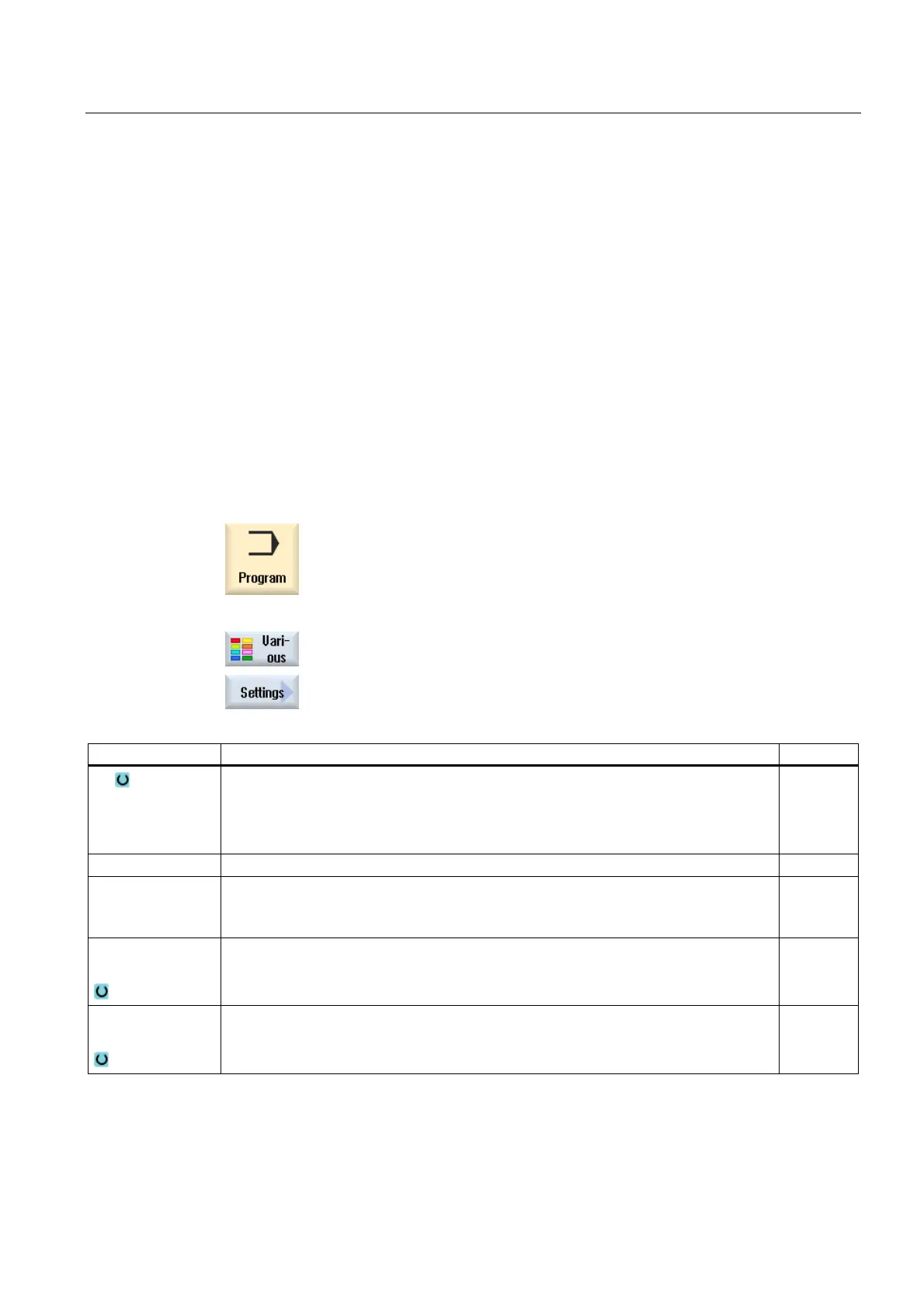
1. Select the "Program" operating area.
2. Press the "Various" and "Settings" softkeys.
The "Settings" input window opens.
Parameter Description Unit
PL Machining plane
G17 (XY)
G18 (ZX)
G19 (YZ)
RP Retraction plane (abs) mm
SC Safety clearance (inc)
Acts in relation to the reference point. The direction in which the safety clearance is
effective is automatically determined by the cycle.
mm
Machining
direction
Milling direction:
Climbing
Conventional
Retraction position
pattern
Lift mode before new infeed
to RP
optimized
mm

 Loading...


