Creating a ShopMill program
7.3 Basic information
Milling
224 Operating Manual, 03/2010, 6FC5398-7CP20-1BA0
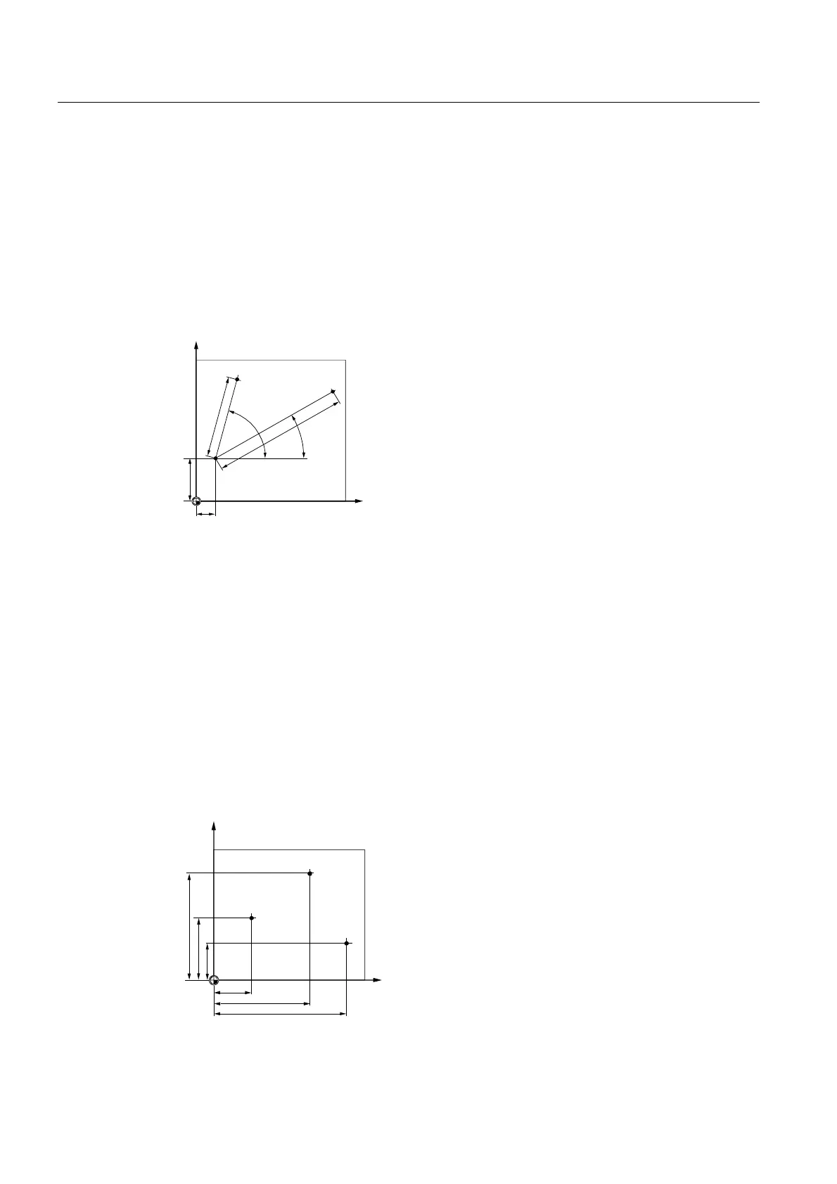
7.3.2 Polar coordinates
The rectangular coordinate system is suitable in cases where dimensions in the production
drawing are orthogonal. For workpieces dimensioned with arcs or angles, it is better to
define positions using polar coordinates. This is possible if you are programming a straight
line or a circle.
Polar coordinates have their zero point at the "pole".
Example
3RO
r
r
3
3
<
;
Points P1 and P2 can then be described – with reference to the pole – as follows:
P1:Radius =100 / angle =30°
P2:Radius =60 / angle =75°
7.3.3 Absolute and incremental dimensions
Absolute dimensions
With absolute dimensions, all the position specifications refer to the currently valid zero
point. Applied to tool movement this means: The absolute dimension data defines the
position, to which the tool is to travel.
Example
3
3
3
<
;

 Loading...


