Programming technological functions (cycles)
8.5 Contour turning - only for G code programs
Milling
400 Operating Manual, 03/2010, 6FC5398-7CP20-1BA0
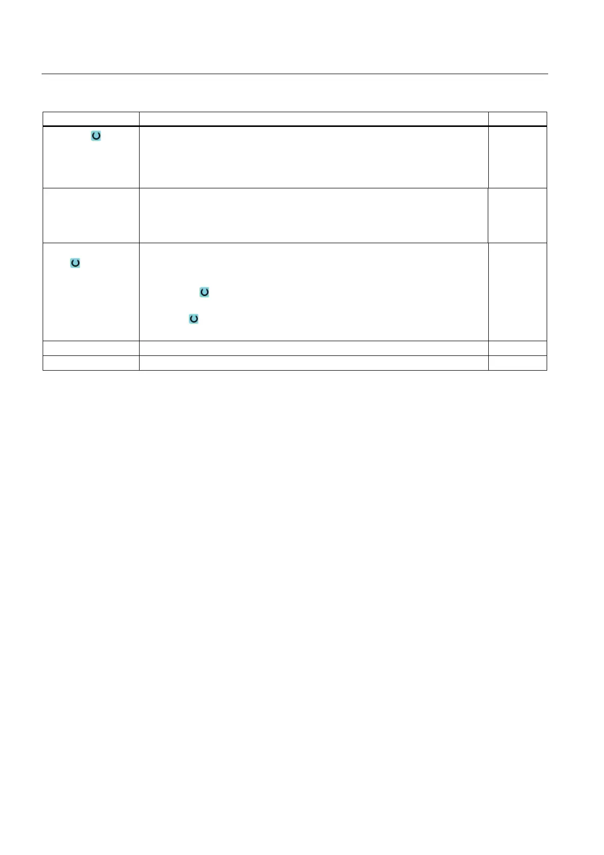
Parameters Description Unit
Allowance Allowance for pre-finishing - (only for ∇∇∇)
Yes
U1 contour allowance
No
mm
U1 Compensation allowance in X and Z direction (inc) – (only for allowance)
Positive value: Compensation allowance is kept
Negative value: Compensation allowance is removed in addition to finishing
allowance
mm
Set machining area
limits
Set machining area limits
Yes
– XA: 1. Limit XA ∅
– XB: 2. 2nd limit XB ∅ (abs) or 2nd limit referred to XB (inc)
– ZA: 1. Limit ZA
– ZB:
2nd limit ZB (abs) or 2nd limit referred to ZB
No
N Number of grooves
DP Distance between grooves (inc) mm
8.5.11 Plunge turning (CYCLE952)
Function
Using the "Plunge turning" function, you can machine any shape of groove.
Contrary to grooving, the plunge turning function removes material on the sides after the
groove has been machined in order to reduce machining time. Contrary to stock removal, the
plunge turning function allows you to machine contours that the tool must enter vertically.
You will need a special tool for plunge turning. Before you program the "Plunge turning"
cycle, you must define the contour.
Set machining area limits
If, for example, you want to machine a certain area of the contour with a different tool, you
can set machining area limits so that machining only takes place in the area of the contour
you have selected.
Feedrate interruption
To prevent the occurrence of excessively long chips during machining, you can program a
feedrate interruption.

 Loading...


