Programming technological functions (cycles)
8.3 Contour milling
Milling
342 Operating Manual, 03/2010, 6FC5398-7CP20-1BA0
Parameter Description Unit
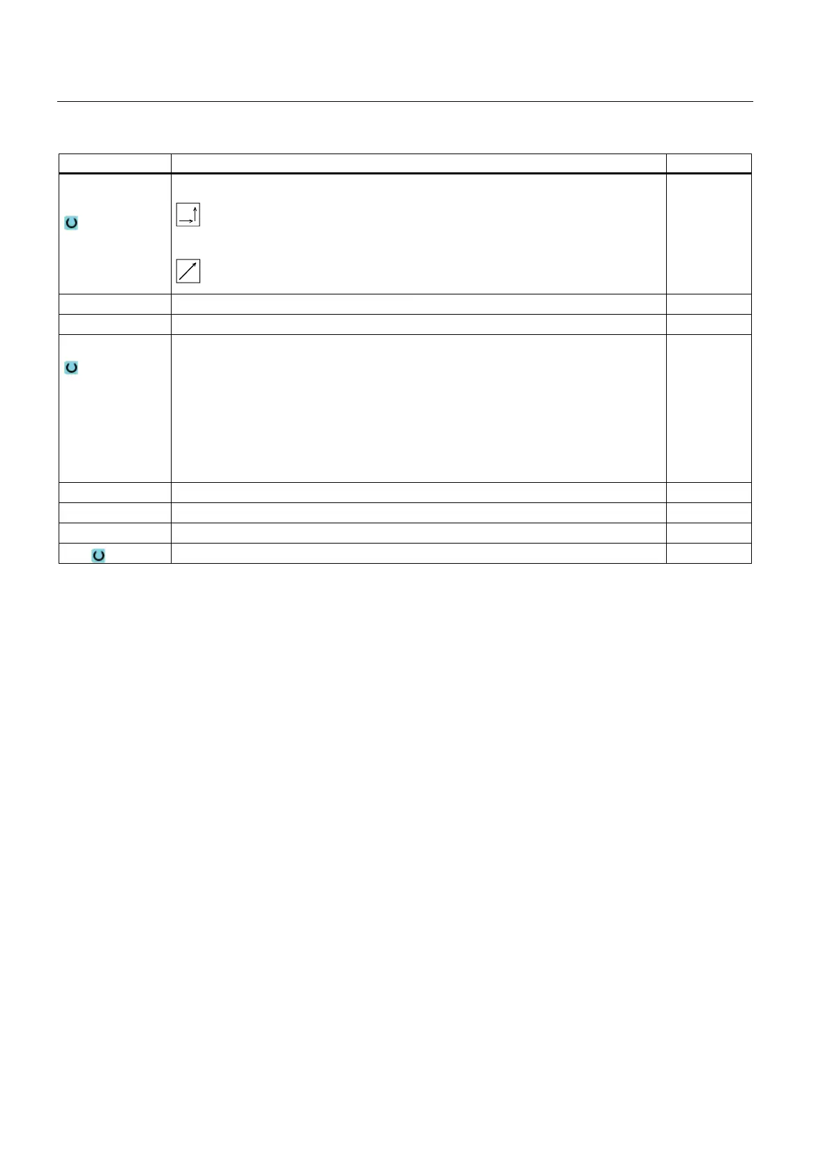
Retraction
strategy
Axis by axis
Spatial (not with perpendicular approach mode)
R2 Retraction radius - (only for "quadrant or semi-circle" retraction) mm
L2 Retraction distance - (only for "straight line" retraction) mm
Lift mode
If more than one depth infeed is necessary, specify the retraction height to which the
tool retracts between the individual infeeds (at the transition from the end of the contour
to the start).
Lift mode before new infeed
Z0 + safety clearance
By the safety clearance
to RP
No retraction
FZ Depth infeed rate - (only for G code)
FR Retraction feedrate for intermediate positioning - (not with "No retraction" lift mode)
FS Chamfer width for chamfering - (only for chamfering machining) mm
ZFS Insertion depth of tool tip (abs or inc) - (for machining only) mm
8.3.8 Contour pocket/contour spigot (CYCLE63/64)
Contours for pockets or islands
Contours for pockets or islands must be closed, i.e. the starting point and end point of the
contour are identical. You can also mill pockets that contain one or more islands. The islands
can also be located partially outside the pocket or overlap each other. The first contour you
specify is interpreted as the pocket contour and all the others as islands.
Automatically calculating/Manually entering the starting point
Using "Automatic starting point" you have the option of calculating the optimum plunge point.
By selecting "Manual starting point", you define the plunge point in the parameter screen.
If the islands and the miller diameter, which must be plunged at various locations, are
obtained from the pocket contour, then the manual entry only defines the first plunge point;
the remaining plunge points are automatically calculated.
Contours for spigots
Contours for spigots must be closed, i.e. the starting point and end point of the contour are
identical. You can define multiple spigots, which can also overlap. The first contour specified
is interpreted as a blank contour and all others as spigots.
 Loading...


