Programming technological functions (cycles)
8.2 Milling
Milling
Operating Manual, 03/2010, 6FC5398-7CP20-1BA0
303
Parameter Description Unit
X0
Y0
Z0
The positions refer to the reference point:
Reference point X – (for single position only)
Reference point Y – (for single position only)
Reference point Z – (for single position only)
mm
mm
mm
∅ Diameter of spigot mm
L Length of spigot mm
R Corner radius mm
α0 Angle of rotation Degrees
Z1 Spigot depth (abs) or depth relative to Z0 (inc) - (only for ∇ and ∇∇∇) mm
DZ Maximum depth infeed - (only for ∇ and ∇∇∇) mm
UXY Plane finishing allowance for the length (L) and width (W) of the circular spigot.
Smaller circular spigot dimensions are obtained by calling the cycle again and
programming it with a lower finishing allowance. - (only for ∇ and ∇∇∇)
mm
UZ Depth finishing allowance (tool axis) - (only for ∇ and ∇∇∇) mm
∅1 Diameter of blank spigot (important for determining approach position) - (only for ∇ and
∇∇∇)
mm
FS Chamfer width for chamfering - (for chamfering only) mm
ZFS Insertion depth of tool tip (abs or inc) - (for chamfering only) mm
8.2.6 Multi-edge (CYCLE79)
Function
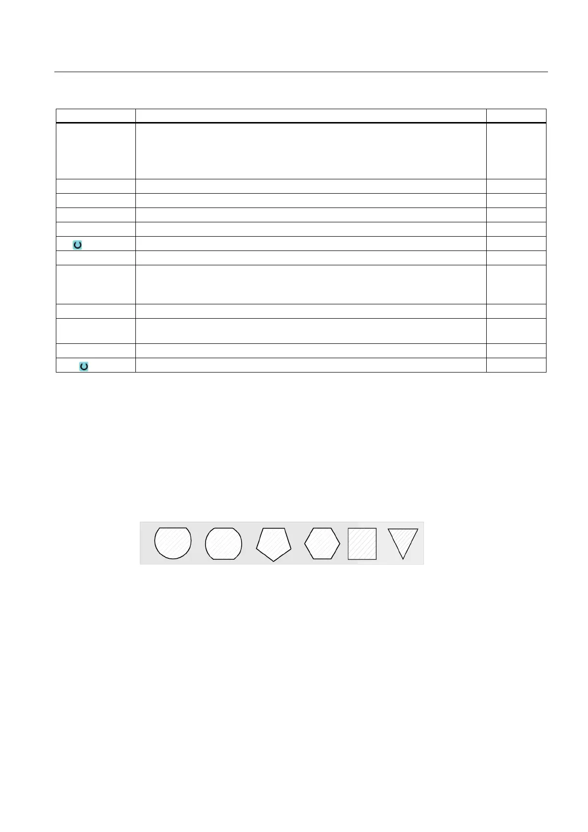
You can mill a multi-edge with any number of edges with the "Multi-edge" cycle.
You can select from the following shapes with or without a corner radius or chamfer:
Approach/retraction
1. The tool approaches the starting point at rapid traverse at the height of the retraction
plane and is fed in to the safety clearance.
2. The tool traverses the multi-edge in a quadrant at machining feedrate. The tool first
executes infeed at machining depth and then moves in the plane. The multi-edge is
machined depending on the programmed machining direction (up-cut/down-cut) in a
clockwise or counterclockwise direction.
3. When the first plane has been machined, the tool retracts from the contour in a quadrant
and then infeed to the next machining depth is performed.
 Loading...


