EasyManuals Logo

Siemens SINUMERIK 840D Operating Manual

Siemens SINUMERIK 840D
610 pages
To Next Page IconTo Next Page
To Previous Page IconTo Previous Page
Page #223 background imageLoading...
Page #223 background image
Creating a ShopMill program
7.3 Basic information
Milling
Operating Manual, 03/2010, 6FC5398-7CP20-1BA0
223
7.3 Basic information
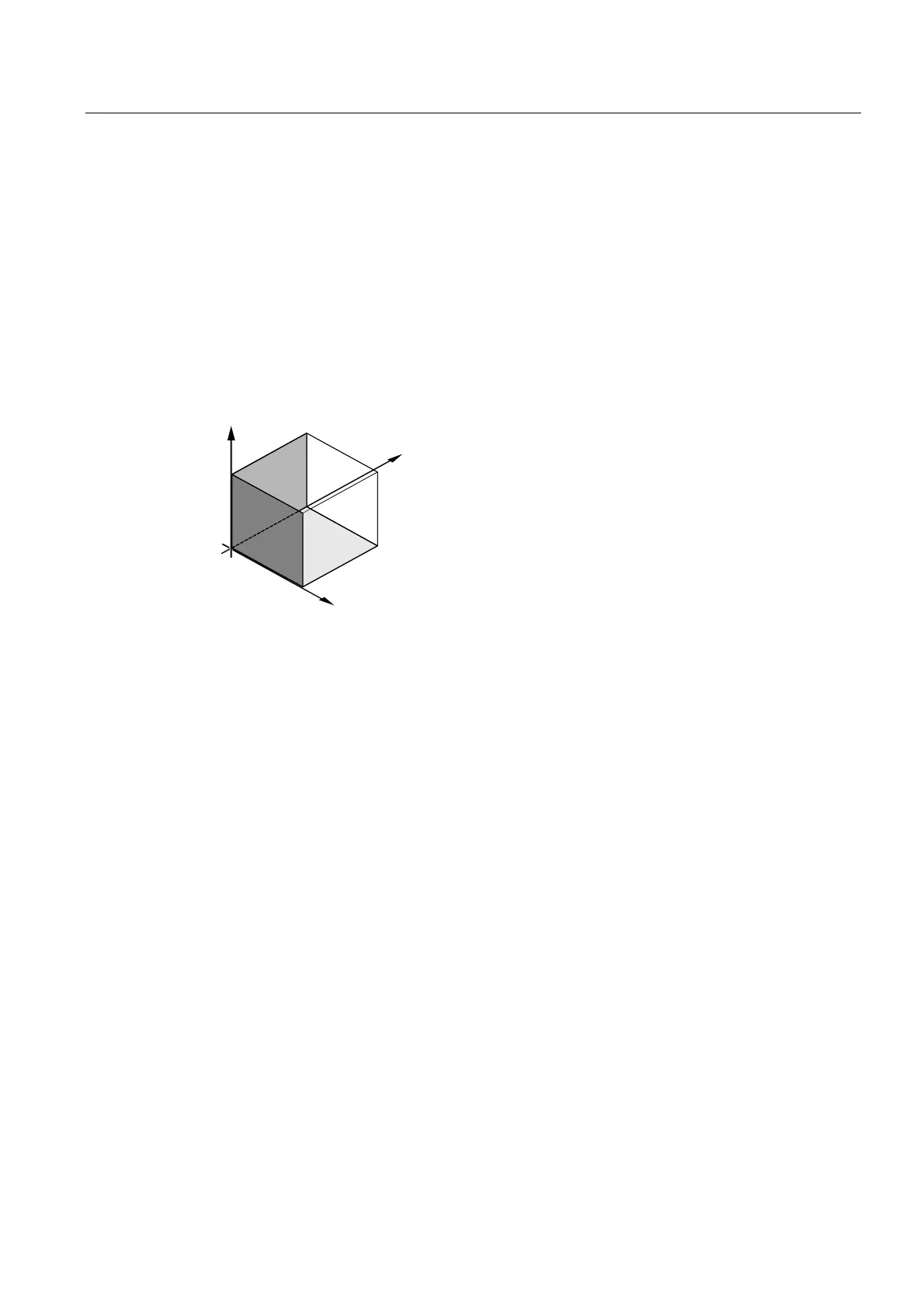
7.3.1 Machining planes
A plane is defined by means of two coordinate axes. The third coordinate axis (tool axis) is
perpendicular to this plane and determines the infeed direction of the tool (e.g. for 2½-D
machining).
When programming, it is necessary to specify the working plane so that the control system
can calculate the tool offset values correctly. The plane is also relevant to certain types of
circular programming and polar coordinates.
;
<
=
<
=
=
;
;
<
Working planes
Working planes are defined as follows:
Plane Tool axis
X/Y G17 Z
Z/X G18 Y
Y/Z G19 X

Table of Contents

Other manuals for Siemens SINUMERIK 840D

Questions and Answers:

Question and Answer IconNeed help?

Do you have a question about the Siemens SINUMERIK 840D and is the answer not in the manual?

Siemens SINUMERIK 840D Specifications

General IconGeneral
SeriesSINUMERIK 840D
AxesUp to 31
ChannelsUp to 10
Operating SystemWindows-based
Power Supply24 V DC
Control Unit TypeCNC
InterfaceEthernet, PROFIBUS
DisplayTFT color display
InterpolationSpline
PLCIntegrated PLC
Data StorageCompactFlash, USB

Related product manuals