Programming technological functions (cycles)
8.1 Drilling
Milling
274 Operating Manual, 03/2010, 6FC5398-7CP20-1BA0
6. Retraction with G0 to the safety clearance of the reference point.
7. Retraction to retraction plane with G0 to drilling position in the two axes of the plane
(coordinates of the hole center point).
Procedure
1. The part program or ShopMill program to be processed has been
created and you are in the editor.
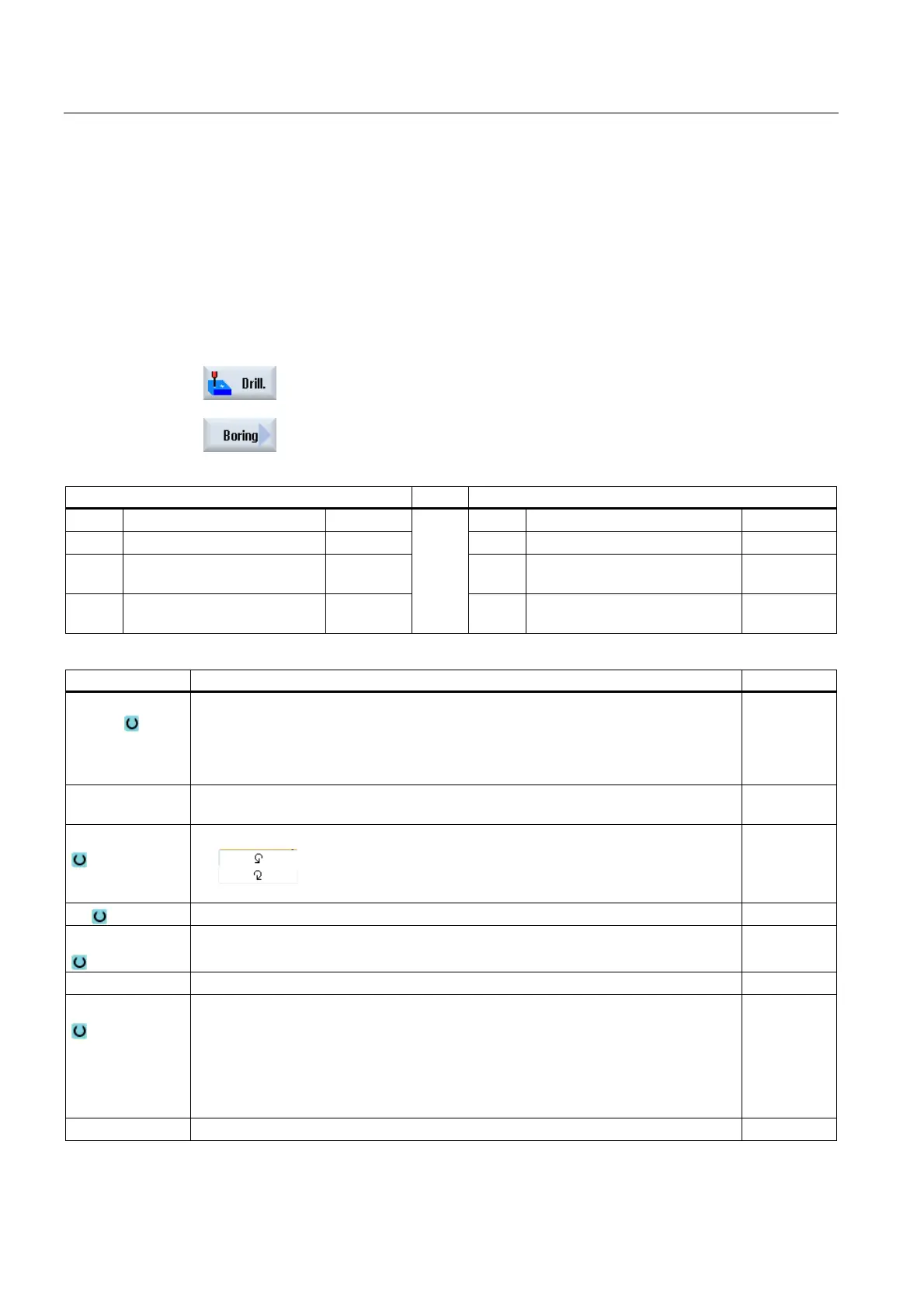
2. Press the "Drilling" softkey.
3. Press the "Boring" softkey.
The "Boring" input window opens.
Parameters, G code program Parameters, ShopMill program
PL Machining plane T Tool name
RP Retraction plane mm D Cutting edge number
SC Safety clearance mm F Feedrate mm/min
mm/rev
S / V Spindle speed or constant
cutting rate
rpm
m/min
Parameter Description Unit
Machining
position (only
for G code)
Single position
Drill hole at programmed position
Position pattern
Position with MCALL
Z0 (only for G
code)
Reference point Z mm
DIR
(only for G
code)
Direction of rotation
Z1 Drilling depth (abs) or drilling depth in relation to Z0 (inc) mm
DT
Dwell time at final drilling depth in seconds
Dwell time at final drilling depth in revolutions
s
rev
SPOS Spindle stop position Degrees
Lift mode
Do not lift off contour
The cutting edge is not fully retracted, but traverses back to the retraction plane.
Lift off contour
The cutting edge retracts from the edge of the hole and then retracts to the safety
clearance from the reference point and then positions at the retraction plane and
hole center point.
DX Retraction distance in the X direction (incremental) - (for lift-off only, standard)

 Loading...


