Programming technological functions (cycles)
8.2 Milling
Milling
Operating Manual, 03/2010, 6FC5398-7CP20-1BA0
291
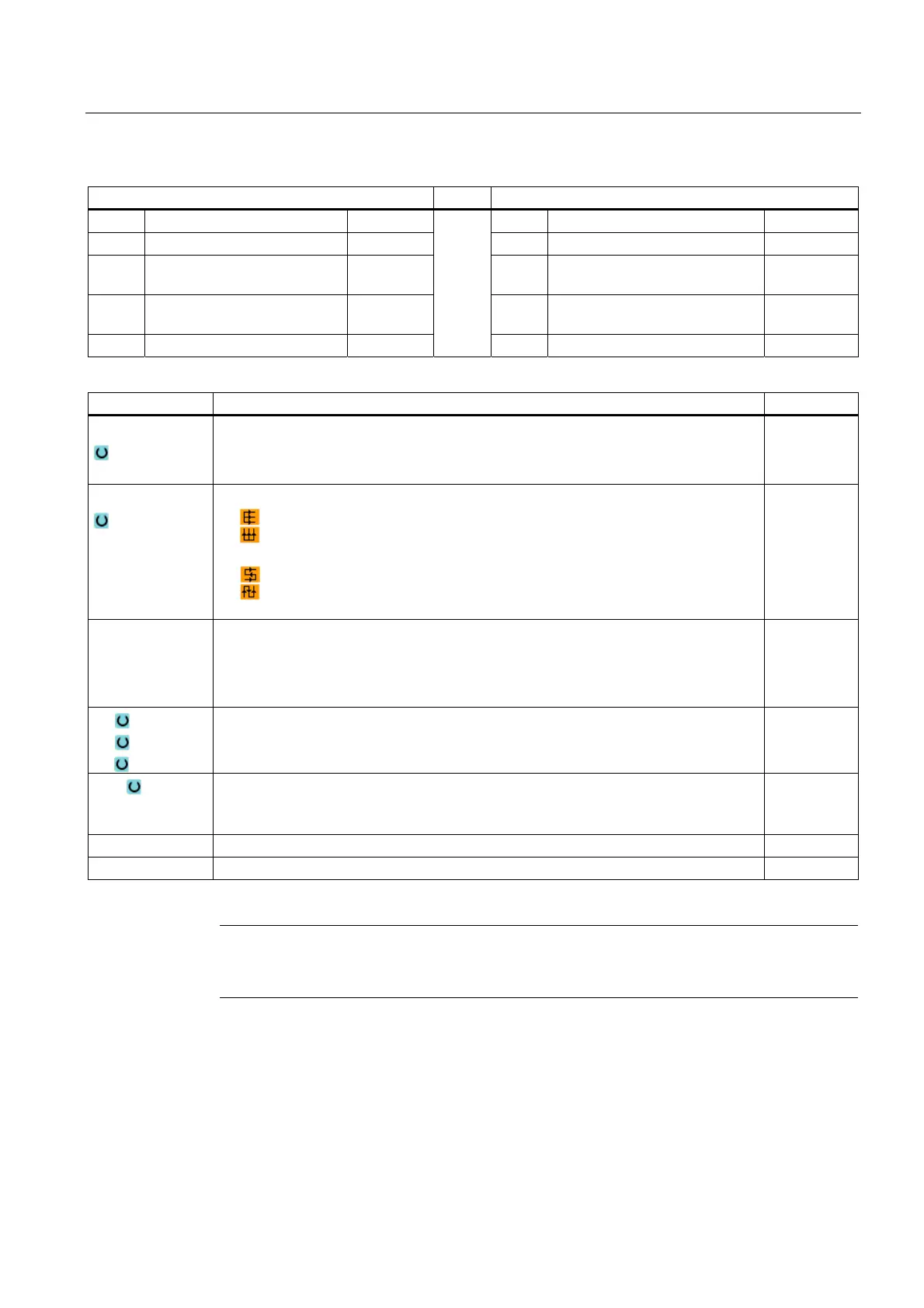
Parameters, G code program Parameters, ShopMill program
PL Machining plane T Tool name
Milling direction D Cutting edge number
RP Retraction plane mm F Feedrate mm/min
mm/rev
SC Safety clearance mm S / V Spindle speed or constant
cutting rate
rpm
m/min
F Feedrate mm/min
Parameter Description Unit
Machining
The following machining operations can be selected:
∇ (roughing)
∇∇∇ (finishing)
Direction
Same direction of machining
Alternating direction of machining
X0
Y0
Z0
The positions refer to the reference point:
Corner point 1X
Corner point 1Y
Height of blank
mm
mm
mm
X1
Y1
Z1
Corner point 2X (abs) or corner point 2X in relation to X0 (inc)
Corner point 2Y (abs) or corner point 2Y in relation to Y0 (inc)
Height of blank (abs) or height of blank in relation to Z0 (inc)
DXY Maximum plane infeed
Alternately, you can specify the plane infeed in %, as a ratio → plane infeed (mm) to the
milling cutter diameter (mm).
mm
%
DZ Maximum depth infeed – (for roughing only) mm
UZ Finishing allowance, depth mm
Note
The same finishing allowance must be entered for both roughing and finishing. The finishing
allowance is used to position the tool for retraction.

 Loading...


