Programming technological functions (cycles)
8.2 Milling
Milling
Operating Manual, 03/2010, 6FC5398-7CP20-1BA0
297
Procedure
1. The part program or ShopMill program to be processed has been
created and you are in the editor.
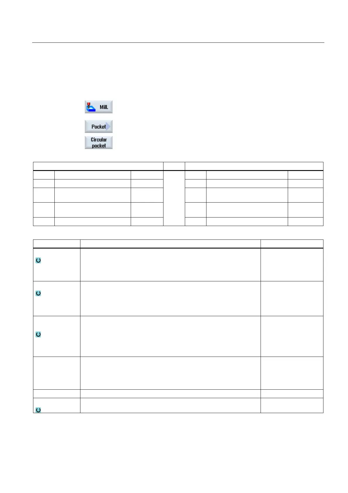
2. Press the "Milling" softkey.
3. Press the "Pocket" and "Circular pocket" softkeys.
The "Circular Pocket" input window opens.
Parameters, G code program Parameters, ShopMill program
PL Machining plane T Tool name
Milling direction D Cutting edge number
RP Retraction plane mm F Feedrate mm/min
mm/rev
SC Safety clearance mm S / V Spindle speed or constant
cutting rate
rev/min
m/min
F Feedrate mm/min
Parameters Description Unit
Machining
∇ (roughing, plane-by-plane or helical)
∇∇∇ (finishing, plane-by-plane or helical)
∇∇∇ edge (edge finishing, plane-by-plane or helical)
Chamfering
Machining type
Plane-by-plane
Machine circular pocket plane-by-plane
Helical
Machine circular pocket using helical type
Machining
position
Single position
A circular pocket is machined at the programmed position (X0, Y0, Z0).
Position pattern
Several circular pockets are machined in a position pattern
(e.g. full circle, pitch circle, grid, etc.).
X0
Y0
Z0
The reference points refer to the center point of the circular pocket:
Reference point X – (for single position only)
Reference point Y – (for single position only)
Reference point Z – (for single position only)
mm
mm
mm
∅ Diameter of pocket mm
Z1
Pocket depth (abs) or depth relative to Z0 (inc) – (only for ∇, ∇∇∇ and ∇∇∇
edge)
mm

 Loading...


