Programming technological functions (cycles)
8.2 Milling
Milling
300 Operating Manual, 03/2010, 6FC5398-7CP20-1BA0
Procedure
1. The part program or ShopMill program to be processed has been
created and you are in the editor.
2. Press the "Milling" softkey.
3. Press the "Multi-edge spigot" and "Rectangular spigot" softkeys.
The "Rectangular Spigot" input window opens.
Parameters, G code program Parameters, ShopMill program
PL Machining plane T Tool name
Milling direction D Cutting edge number
RP Retraction plane mm (in) F Feedrate mm/min
mm/rev
SC Safety clearance mm S / V Spindle speed or constant
cutting rate
rpm
m/min
F Feedrate mm/min
Parameter Description Unit
FZ
(only for G code)
Depth infeed rate mm/min
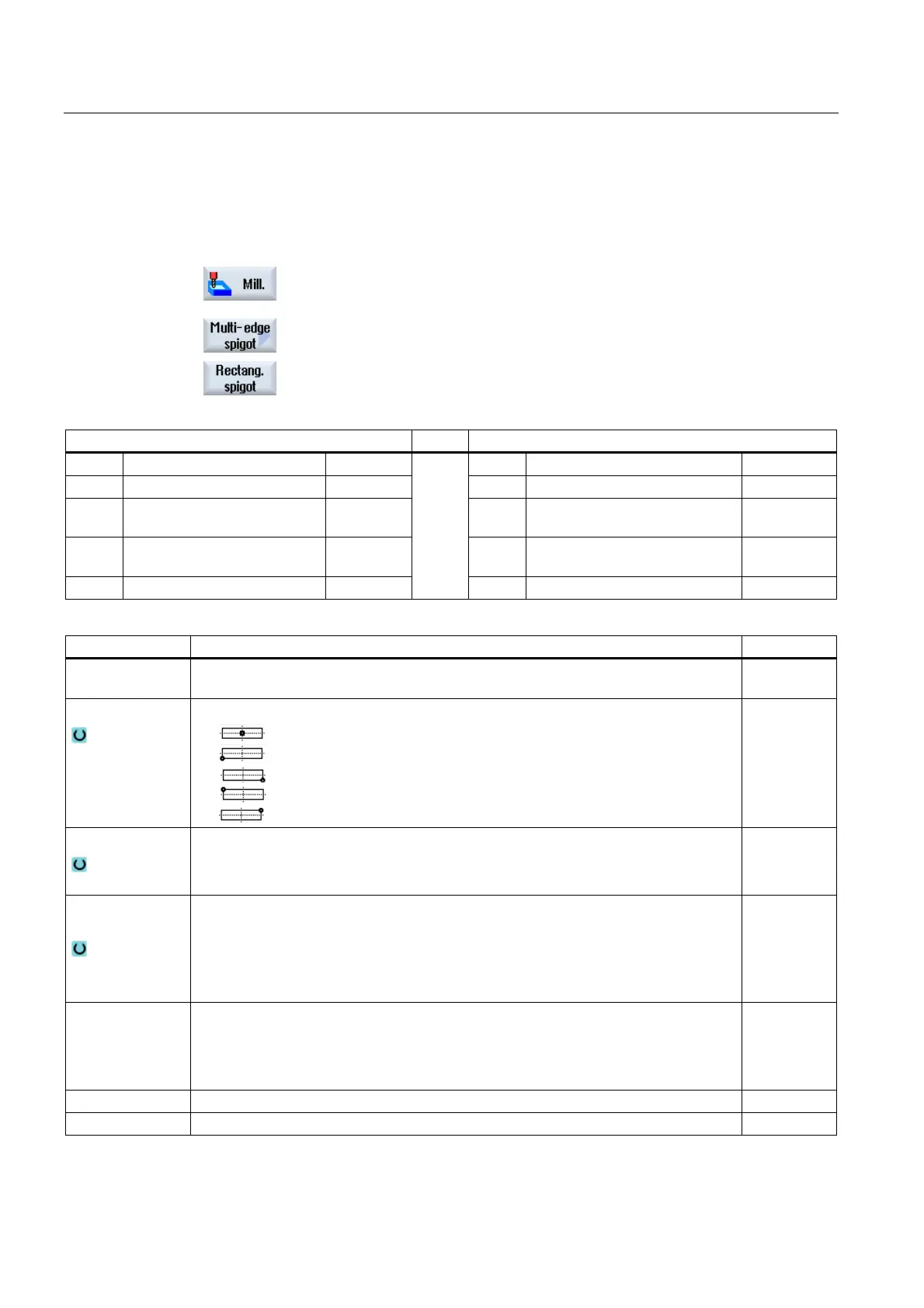
Reference point
The following different reference point positions can be selected:
(center)
(bottom left)
(bottom right)
(top left)
(top right)
Machining
∇ (roughing)
∇∇∇ (finishing)
Chamfering
Machining
position
Single position
A rectangular spigot is machined at the programmed position (X0, Y0, Z0).
Position pattern
Several rectangular spigots are machined in a position pattern
(e.g. full circle, pitch circle, grid, etc.).
X0
Y0
Z0
The positions refer to the reference point:
Reference point X – (for single position only)
Reference point Y – (for single position only)
Reference point Z – (for single position only)
mm
mm
mm
W Width of spigot mm
L Length of spigot mm

 Loading...


