Programming technological functions (cycles)
8.3 Contour milling
Milling
Operating Manual, 03/2010, 6FC5398-7CP20-1BA0
329
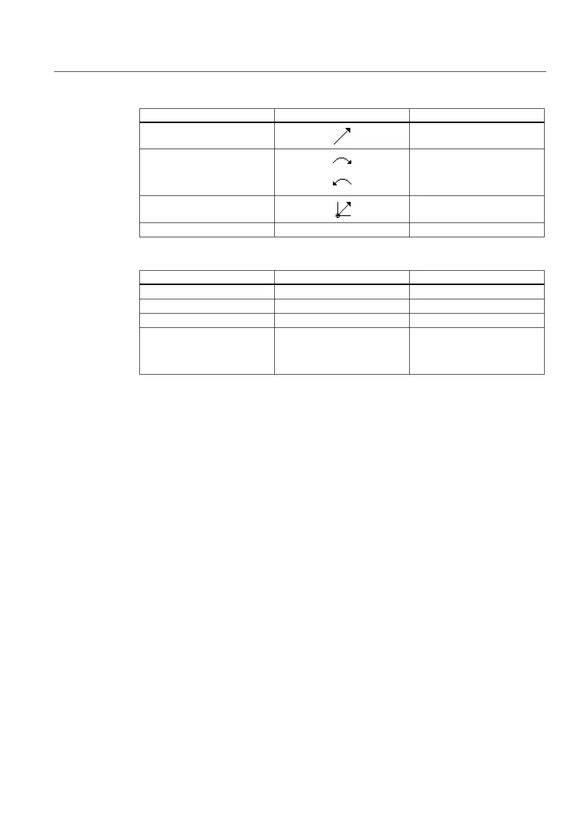
Contour element Symbol Meaning
Straight line in any direction
Straight line with any gradient
Arc right
Arc left
Circle
Circle
Pole
Straight diagonal or circle in
polar coordinates
Finish contour END End of contour definition
The different colors of the symbols indicate their status:
Foreground Background Meaning
Black Blue Cursor on new element
Black Orange Cursor on current element
Black White Normal element
Red White Element not currently evaluated
(element will only be evaluated
when it is selected with the
cursor)
Graphical display
The progress of contour programming is shown in broken-line graphics while the contour
elements are being entered.
When the contour element has been created, it can be displayed in different line styles and
colors:
● Black: Programmed contour
● Orange: Current contour element
● Green dashed: Alternative element
● Blue dotted: Partially defined element
The scaling of the coordinate system is adjusted automatically to match the complete
contour.
The position of the coordinate system is displayed in the graphics window.

 Loading...


