Programming technological functions (cycles)
8.3 Contour milling
Milling
352 Operating Manual, 03/2010, 6FC5398-7CP20-1BA0
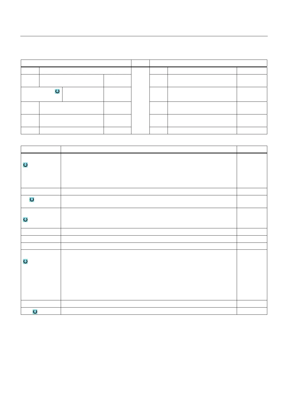
Parameters, G code program Parameters, ShopMill program
PRG Name of the program to be generated T Tool name
PL Machining plane F Feedrate mm/min
mm/rev
Milling direction
Climbing
Conventional
D Cutting edge number D
RP Retraction plane mm F Feedrate mm/min
mm/rev
SC Safety clearance mm S / V Spindle speed or constant
cutting rate
rpm
m/min
F Feedrate mm/min
Parameter Description Unit
Machining
The following machining operations can be selected:
∇ (roughing)
∇∇∇ base (base finishing)
∇∇∇ edge (edge finishing)
Chamfering
Z0 Reference point Z mm
Z1 Pocket depth (abs) or depth relative to Z0 (inc)
- (only for ∇, ∇∇∇ base or ∇∇∇ edge)
mm
DXY
Maximum plane infeed
Maximum plane infeed as a percentage of the milling cutter diameter
- (only for ∇ and ∇∇∇ base)
mm
%
DZ Maximum depth infeed – (only for ∇ or ∇∇∇ edge) mm
UXY Plane finishing allowance – (only for ∇, ∇∇∇ base or ∇∇∇ edge) mm
UZ Depth finishing allowance – (only for ∇ or ∇∇∇ base) mm
Lift mode
Lift mode before new infeed
If the machining operation requires several points of insertion, the retraction height can
be programmed:
to RP
Z0 + safety clearance
When making the transition to the next insertion point, the tool returns to this height. If
there are no elements larger than Z0 (X0) in the pocket area, then Z0 (X0) + safety
clearance can be programmed as the lift mode.
mm
mm
mm
FS Chamfer width for chamfering - (only for chamfering machining) mm
ZFS Insertion depth of tool tip (abs or inc) - (for machining only) mm

 Loading...


