VA Motion Controller Programming Manual
12
III PLC Working Principle
3.1 PLC Executing the Program Written by the User
Users download the program to the PLC and run PLC. The motion controller can cycle
through the user's program. The program is not executed when the CPU is stopped. Each time the
PLC executes the user's program, it is calleDA scan cycle, and the following work will be
performed in one scan cycle:
A] Read Input: digital, analog input signals read into the input mapping area.
B] Execution program: executing a user's instruction and the intermediate, the final data
stored in the various memory areas.
C] Processing any communications requests: to monitor communications.
D] CPU self-diagnosis: Check the firmware, the program memory working condition.
E] Write output: the stored data is copied to the physical output point in the output of the
mapping area.
Note: If you want to implement a periodic task when you execute a program at regular
intervals, instead of using a timer to trigger a periodic pulse in the cyclic scan task, the former
should be accurate.
3.2 PLC Data Access
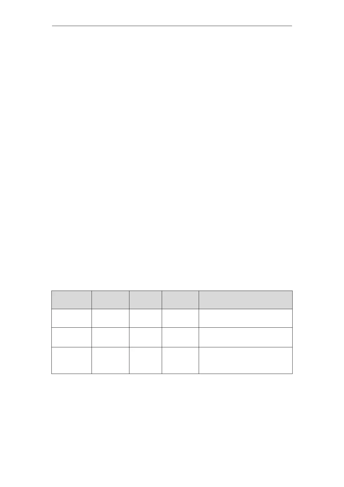
1) The users’ data can be stored in different memory cells of the PLC, each cell has a unique
address. The following table lists the different sizes of data that can be represented range of
values;
-2147483648 to +2147483647
+ 1.175495E-38 to 34,022,823
-1.175495E-38 to 34,022,823
2) For data access, you must specify the address, the address starts with %, followed by the
location prefix, the size prefix, and the byte address with an integer. The decimal point "." is added
to the integer to indicate the bit. For example, %IX0.0 means the input mapping area is 0. The 0th
bit of the byte, the following table is the address characteristics of the data.