VA Motion Controller Programming Manual
287
11.3.5 Analog offset adjustment
Zero drift Definition:Zero drift analog amplifier means when the input signal is zero, the
output is not zero is called zero drift phenomenon. That is: When the input of the amplifier short
circuit, at the output there is an irregular phenomenon generated voltage changes slowly.
The motion controller instruction module zero drift adjustment step; (here, respectively
to servo drive Vector VB and VC will be described servo drive)
Vector VB servo drives:
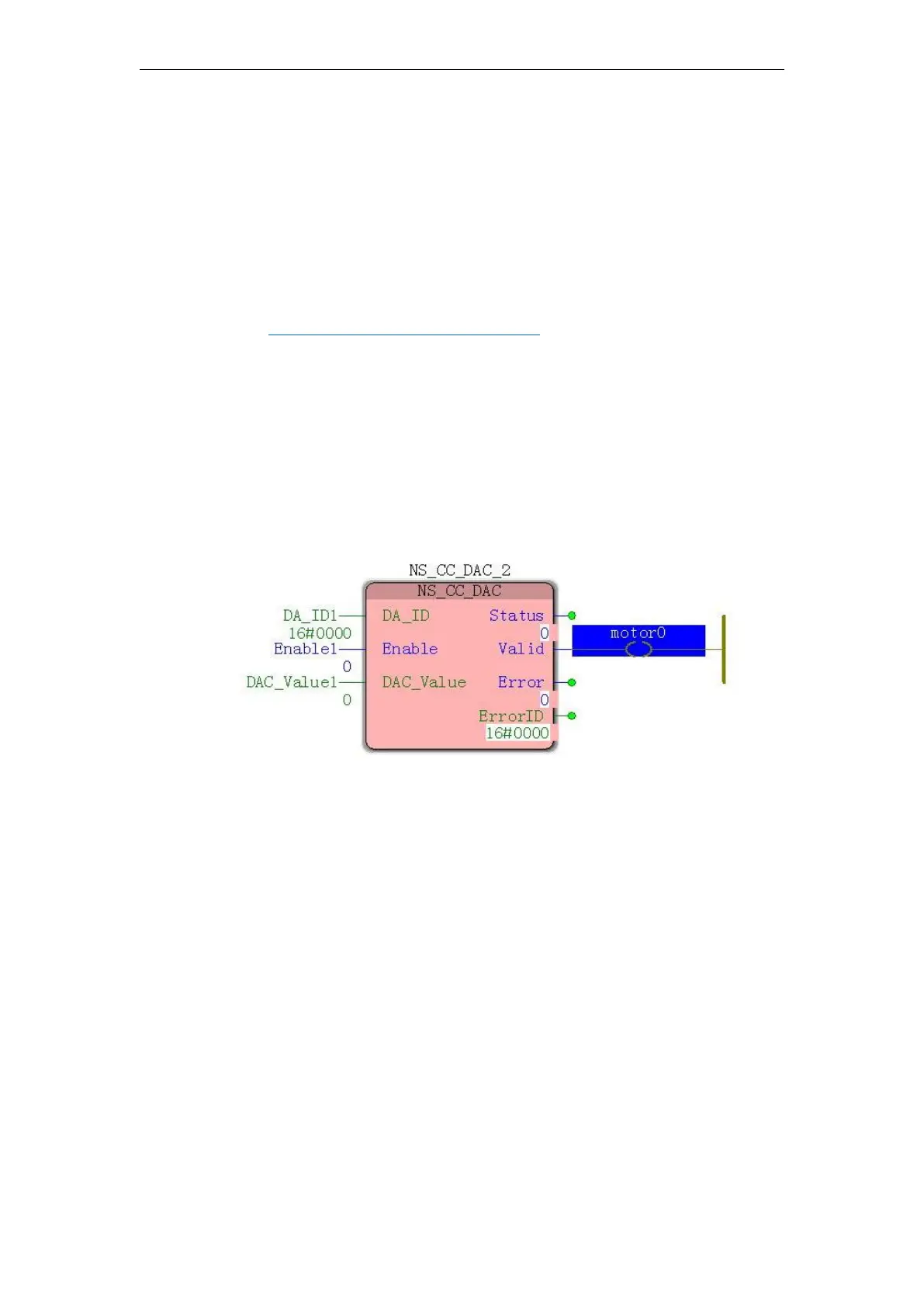
(1) Reference11.6.2 NS_CC_DAC (DA instruction)Instructions and digital to analog
conversion module DA relation, after the completion of programming.
(2) in the Edit Wizard, the callout "NS_CC_DAC" module, where 0 is the adjusting shaft
(Axis0) zero drift, DA_ID initial value fill other axis "0" and so on (0-3), can control multi-axis
simultaneously tune a plurality of "NS_CC_DAC" module.
(3) Fill in the data input module type variable, the variable name can be named their own, but to
ensure that the user name is not duplicated without having to complete the actual physical
address, the software automatically assigned an address. Be downloaded after clicking "Create"
no error when finished.
(4) the online debugging mode, when the Enable becomes FALSE TRUE by the (already in
ensuring the servo enabled state), if the motor is running at the speed of zero drift, DAC_Value
adjustment value at this time to ensure that the servo drive in a stationary state, Enable the TRUE
to FALSE, offset adjustment is completed, and then completing the axis parameters as the initial
value of the value DAC_Value MC_AXIS_REF (axis parameter) of the module Middle_Value.
Vector VC servo drives:
Steps (1), (2), and (3) are the same as the VB servo driver. In step (4), in the online
debugging mode, when Enable is changed from FALSE to TRUE (ensure that the servo is already
enabled), if the motor is at zero speed During operation, the servo P06.68 (AI1 zero drift mV) /
P06.73 (AI2 zero drift mV) / P06.78 (AI3 zero drift mV) is adjusted through the BOP panel to
ensure that the servo drive is at rest, zero drift The adjustment is complete. When filling the axis
parameter, use 0 as the initial value of the MC_AXIS_REF (axis parameter) module
Middle_Value.
note: