282 www.xilinx.com Virtex-6 FPGA GTX Transceivers User Guide
UG366 (v2.5) January 17, 2011
Chapter 5: Board Design Guidelines
Reference Clock Checklist
The following criteria must be met when choosing an oscillator for a design with GTX
transceivers:
• Provide AC coupling between the oscillator output pins and the dedicated Quad
clock input pins.
• Ensure that the differential voltage swing of the reference clock is the range as
specified in the Virtex-6 FPGA Data Sheet (the nominal range is 200 mV – 2000 mV, and
the typical value is 1200 mV).
Note:
These are nominal values. Refer to the Virtex-6 FPGA Data Sheet for exact values and
ranges based on marginal conditions.
• Meet or exceed the reference clock characteristics as specified in the Virtex-6 FPGA
Data Sheet.
• Meet or exceed the reference clock characteristics as specified in the standard for
which the GTX transceiver provides physical layer support.
Note:
An actively toggling reference clock must be supplied to any transceiver that bypasses
the TX or RX buffer at any time. The reference clock can be connected to an internal or external
reference clock source. Refer to TX Buffer Bypass, page 155 and RX Buffer Bypass, page 231
for more information.
• Fulfill the oscillator vendor’s requirement regarding power supply, board layout, and
noise specification.
• Provide a dedicated point-to-point connection between the oscillator and Quad clock
input pins.
• Keep impedance discontinuities on the differential transmission lines to a minimum
(impedance discontinuities generate jitter).
Reference Clock Interface
LVDS
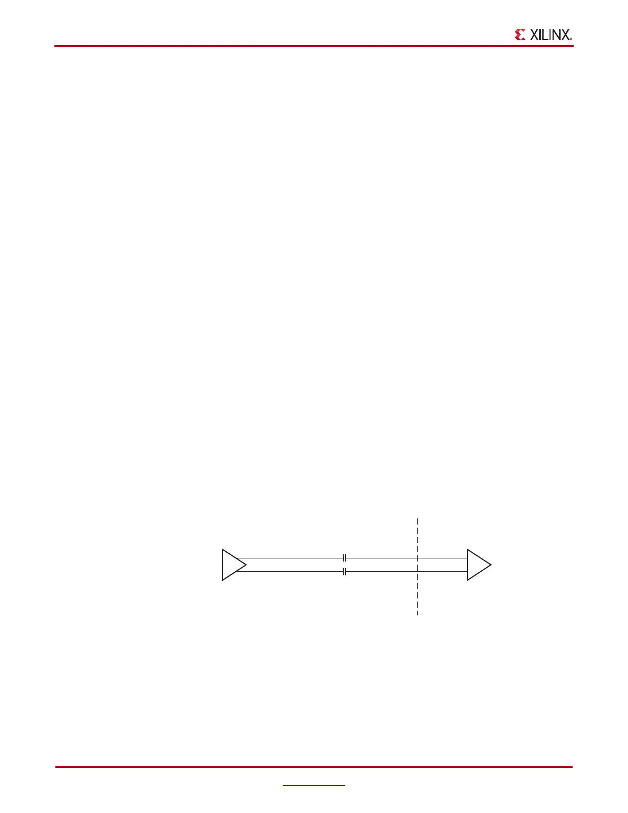
Figure 5-9 shows how an LVDS oscillator is connected to a reference clock input of a GTX
transceiver.
LVPECL
Figure 5-10 shows how an LVPECL oscillator is connected to a reference clock input of a
GTX transceiver. The resistor values given in Figure 5-10 are nominal. Refer to the
oscillator vendor data sheet for actual bias resistor requirement.
X-Ref Target - Figure 5-9
Figure 5-9: Interfacing an LVDS Oscillator to a GTX Transceiver Reference Clock
Input
LVDS Oscillator GTX Transceiver
Reference Clock
Input Buffer
Internal to Virtex-6 FPGA
0.01 µF
0.01 µF
UG366_c5_09_051509

 Loading...

