Virtex-6 FPGA GTX Transceivers User Guide www.xilinx.com 213
UG366 (v2.5) January 17, 2011
RX Polarity Control
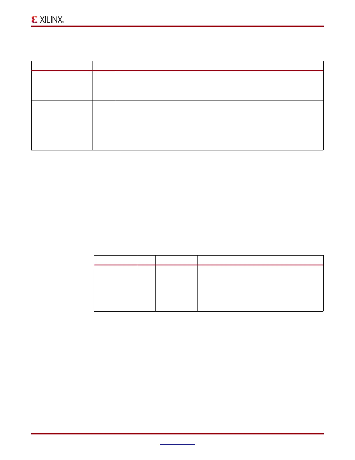
Table 4-27 defines the RX margin analysis attributes.
RX Polarity Control
Functional Description
The GTX RX can invert incoming data using the RX polarity control function. This function
is useful in designs where the RXP and RXN signals can be accidentally connected in
reverse. The RXPOLARITY port is driven High to invert the polarity of incoming data.
Ports and Attributes
Table 4-28 defines the RX polarity control ports.
There are no RX polarity control attributes.
Using RX Polarity Control
If the polarity of RXP/RXN needs to be inverted, RXPOLARITY must be tied High.
Table 4-27: RX Margin Analysis Attributes
Attribute Type Description
RX_EYE_OFFSET 8-bit
Hex
When RX_EYE_SCANMODE = 10 or 01, RX_EYE_OFFSET determines the offset
between the edge sampler, controlled by the CDR, and the data sampler. The valid
range is 0 to 127 (0x00 to 0x7F) which corresponds to the 0 to 1.0 UI position of a
serial data bit.
RX_EYE_SCANMODE 2-bit
Binary
RX_EYE_SCANMODE determines if the receiver should work in normal operation
of in the scan operation.
00: Regular data operation. RX_EYE_OFFSET is ignored.
01: Eye outline scan mode.
10: Horizontal eye margin scan mode.
11: Reserved.
Table 4-28: RX Polarity Control Ports
Port Dir Clock Domain Description
RXPOLARITY In RXUSRCLK2 The RX polarity port can invert the polarity of
incoming data.
0: Not inverted. RXP is positive and RXN is
negative.
1: Inverted. RXP is negative and RXN is
positive.

 Loading...

