186 www.xilinx.com Virtex-6 FPGA GTX Transceivers User Guide
UG366 (v2.5) January 17, 2011
Chapter 4: Receiver
Use Modes – RX Termination
Table 4-3 lists the possible settings for RCV_TERM_GND and RCV_TERM_VTTRX.
Note:
MGTAVTT_* refers to MGTAVTT_S of the south package power plane and MGTAVTT_N of
the north package power plane as outlined in Figure 5-4, page 277.
Table 4-4 outlines the recommended settings for RX termination in Use Mode 1. Figure 4-3
shows the Use Mode 1 configuration.
TERMINATION_CTRL[4:0] 5-bit Binary Controls the internal termination calibration circuit. This is an
advance feature.
TERMINATION_OVRD Boolean Selects whether the external 100 precision resistor connected to the
MGTRREF pin or an override value is used, as defined by
TERMINATION_CTRL[4:0]. This is an advance feature.
Table 4-2: RX AFE Attributes (Cont’d)
Attribute Type Description
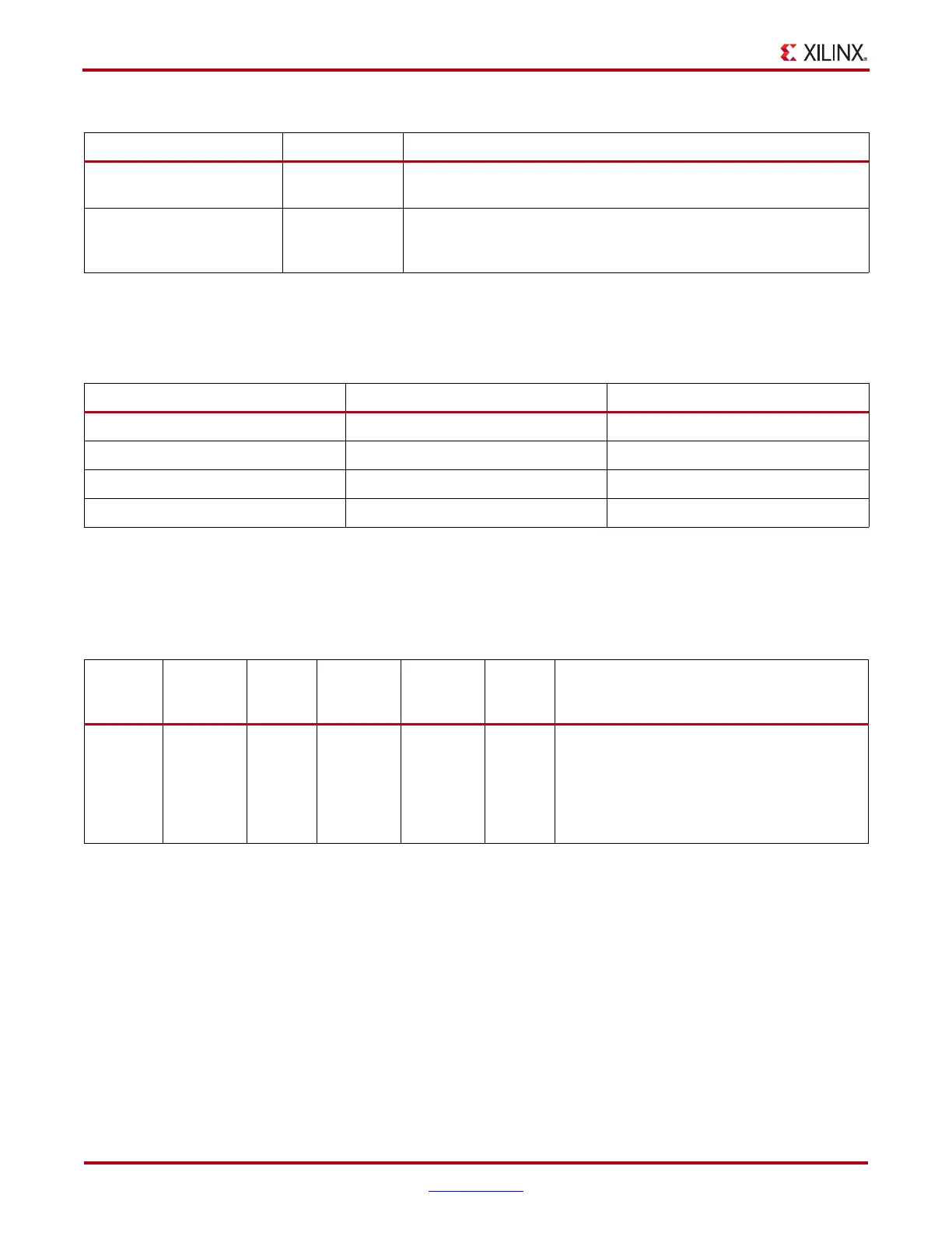
Table 4-3: RX Termination Voltage and Attribute Mapping
RCV_TERM_GND RCV_TERM_VTTRX RX Termination Voltage
FALSE FALSE FLOAT
FALSE TRUE MGTAVTT_*
TRUE FALSE GND
TRUE TRUE RESERVED / NOT ALLOWED
Table 4-4: RX Termination Use Mode 1 Configuration
Use Mode
External
AC
Coupling
Term
Voltage
Internal AC
Coupling
Internal
Bias
Max
Swing
mV
DPP
Suggested Protocols and Usage Notes
1 On GND On 800 mV 1200 Protocol: PCIe
Attribute Settings:
AC_CAP_DIS = FALSE
RCV_TERM_GND = TRUE
RCV_TERM_VTTRX = FALSE

 Loading...

