Virtex-6 FPGA GTX Transceivers User Guide www.xilinx.com 151
UG366 (v2.5) January 17, 2011
TX Gearbox
Internal Sequence Counter Operating Mode
As shown in Figure 3-17, the internal sequence counter operating mode uses the
TXSTARTSEQ input and the TXGEARBOXREADY output in addition to the TXDATA data
inputs and the TXHEADER header inputs. In this use model, the TXSEQUENCE inputs are
not used. The use model is similar to the previous use model except that the
TXGEARBOXREADY output is not used.
The TXSTARTSEQ input indicates to the TX gearbox when the first byte of data after a reset
is valid. TXSTARTSEQ is asserted High when the first byte of valid data is applied after a
reset condition. The TXDATA and TXHEADER inputs must be held stable after reset, and
TXSTARTSEQ must be held Low until data can be applied continuously.
There are no requirements on how long a user can wait before starting to transmit data.
TXSTARTSEQ is asserted High along with the first two bytes/four bytes of valid data and
not before. After the first bytes of data, TXSTARTSEQ can be held at any value that is
convenient.
After data is driven, TXGEARBOXREADY is deasserted Low for either two TXUSRCLK2
cycles (4-byte mode) or three TXUSRCLK2 cycles (2-byte mode). Figure 3-18 and
Figure 3-19 show the behavior of TXGEARBOXREADY for a 4-byte interface and a 2-byte
interface, respectively. When TXGEARBOXREADY is deasserted Low, only one
TXUSRCLK2 cycle remains before the data pipe must be stopped. The one-cycle latency is
fixed and cannot be changed. After one cycle of latency, data must be held through four
bytes (one TXUSRCLK2 cycle for 4-byte mode or two TXUSRCLK2 cycles for 2-byte mode)
and then data is continued to be driven. Only data must be held. TXGEARBOXREADY
transitions High on the cycle where new data must be driven. For this mode of operation,
the number of hold points is identical to when using the external sequence counter mode
for 64B/67B and 64B/66B.
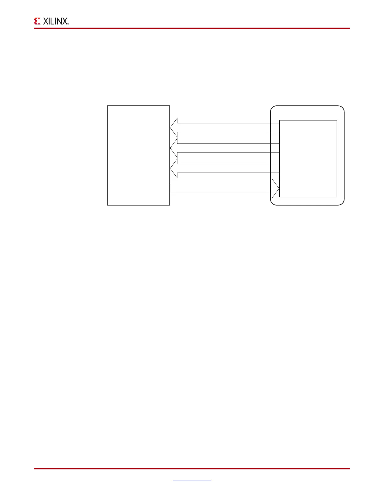
X-Ref Target - Figure 3-17
Figure 3-17: TX Gearbox in Internal Sequence Counter Mode
Data Source
TXGEARBOXREADY
TXHEADER[2:0]
TXDATA[15:0] or TXDATA[31:0]
TX Gearbox
(in GTX Transceiver)
Design in FPGA Logic
UG366_c3_07_051509
TXSTA RT SEQ

 Loading...

